This page documents the construction of the tail wheel for my KR2-S.
9 November, 2004
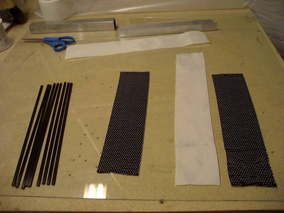
For some strange reason, I decided that I did not want to use the spring steel called for in the plans for the tail wheel spring, so I decided that I would make my own out of carbon fiber (CF). I bought some of the CF rod from Wicks and then proceeded to make the rest up as I went along.
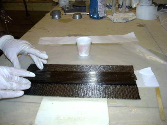
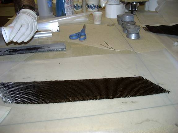
Here is the first layup I did on the spring.
It consists of two layers of uni CF and 9 sections
of CF rod cut to length.
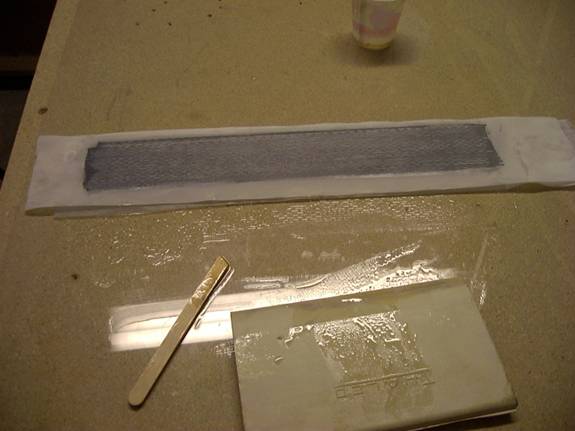
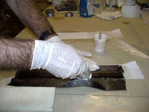
Here the CF rod had been sandwiched between the two layers
of CF uni and peel ply has been used on both sides.
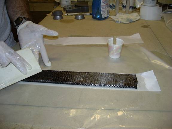
The next layup consists of two more layers of CF uni and
more CF rod.
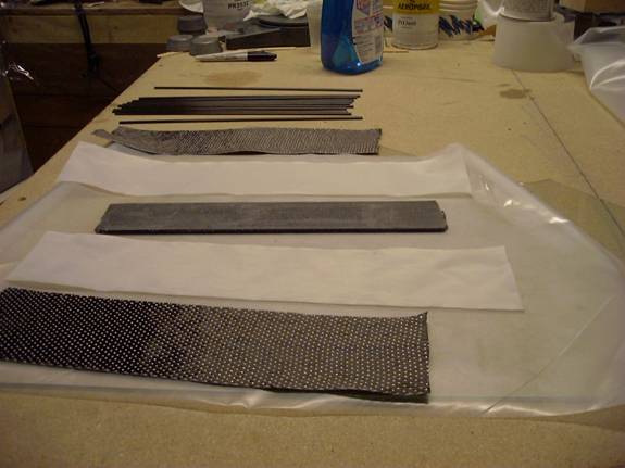
This time the two layers of CF uni are placed side by side
and the first layup is centered on the joint between the two.
The additional CF rods are put down on top of layup 1
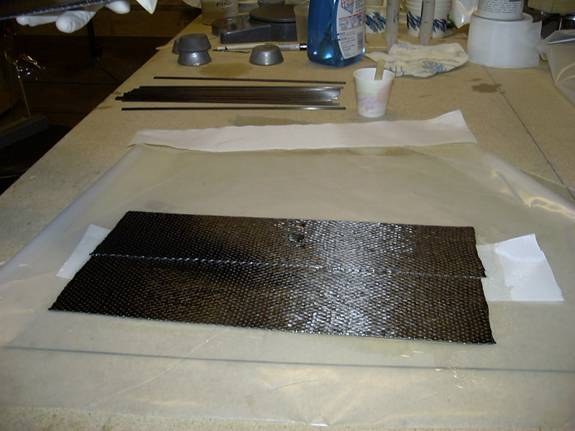
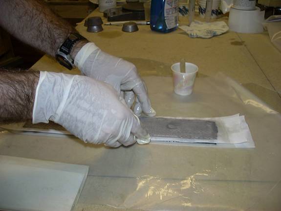
Now the CF uni is wrapped around.
Smoothed out.
Peel ply is applied.
This is the layer of CF bid that was then wrapped around the
whole thing.
The plans call for a solid block to be cut to shape for the tail
wheel block. Wicks wood kit came as a smaller piece that needs
to be laminated before being cut to shape.
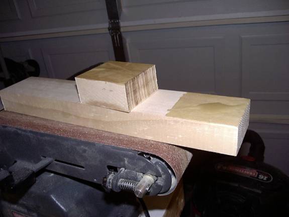
Here it has been laminated and the shape drawn on ready to be cut.
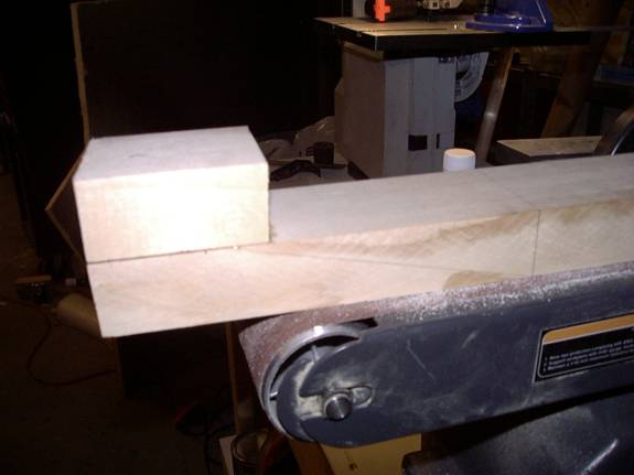
Cut and glued to the fuselage.
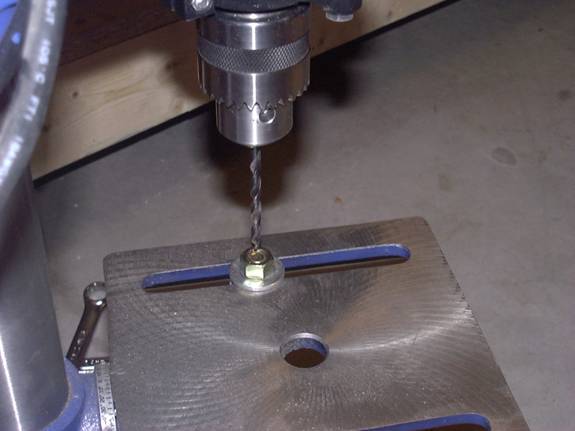
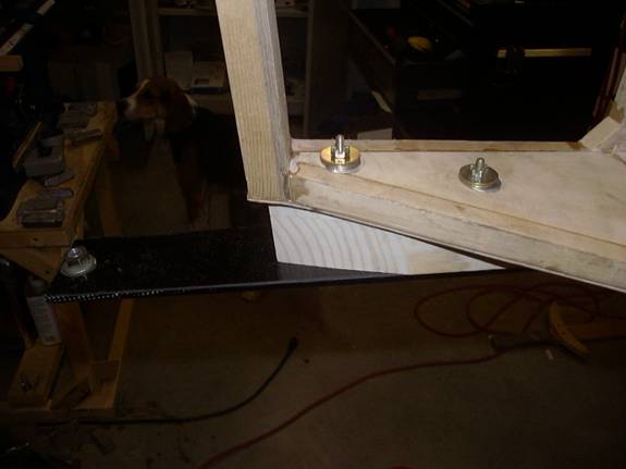
The tail wheel bracket is attached to the spring via an AN3
bolt. In order to give the bolt a larger “bearing surface”
the plans call for a 5/8 inch bolt to be bolted through the
spring with a 3/16th inch hole drilled through it.
Here the bolt is bolted to my drill press table to begin
the drilling process.
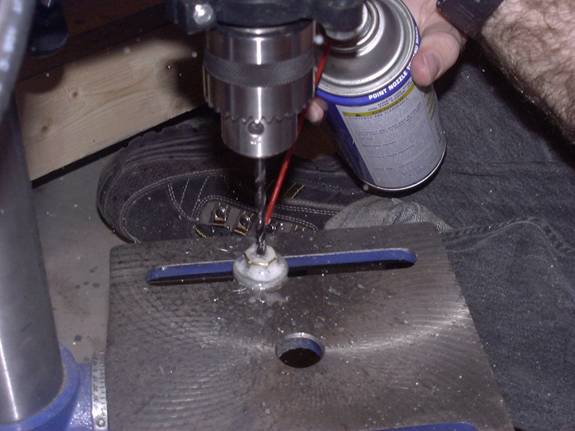
I tried to keep everything cool by using WD40 while
drilling. I forgot to change the speed of my drill press
and discovered that all turning it too fast does is harden
the bolt and ruin drill bits!
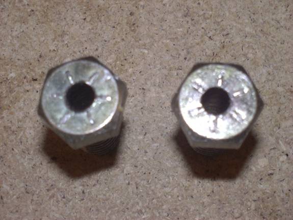
Two of the bolts that made it through the process (there are
at least two more that did not—they got so hard I could not drill them
through). The bolt I’m using was drilled after I discovered my drill
press speed was wrong.
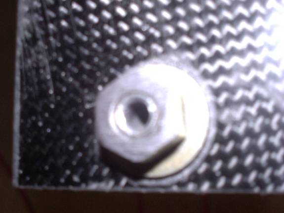
Here it is installed in the tail wheel spring.
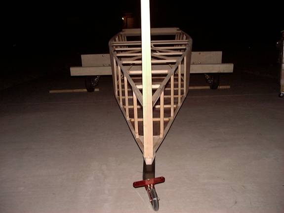
And here everything is bolted (temporarily) to the fuselage.
The aluminum parts all cut out and ready to assemble.
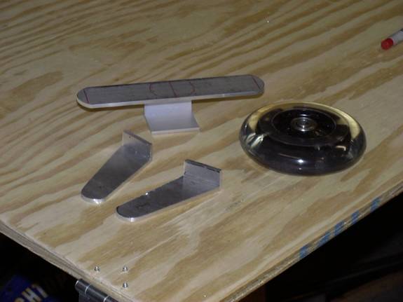
I was going to weld them, however I discovered that gas
welding of aluminum is not my thing, so I’ll stick with bolts for now.
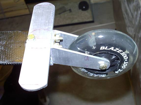
Here it is after it has been anodized and put on the plane.
I did not like the way the bolt tilted to the back.
The whole thing tended to cant to one side or
the other and would not stay in the center.
Here is the first step I took to fix the problem.
I took the bolt out, re-drilled the hole at the angle I
wanted and replaced the bolt with one that was several inches
long. This allowed me to “build up” the area around the
bolt with some flox (there is also a piece of CF rod that runs just
aft of the bolt).
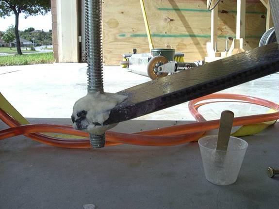
This has since been sanded down and a new layer of CF has been put in place over the whole area. The bolt now is at the proper angle and works much better (more pictures to follow).
Back to main page