On to the next Fuselage page
Back to main page
This page documents the construction of my fuselage.
Change 28 April, 2003---I have elected to post the pictures as is. You can still make them larger by clicking on them,
however, they are now larger in file size. Sorry dial up users.
Project Update: 28 April, 2003
It has been a while since I updated the web page, so this represents all updates since July 12, 2002.
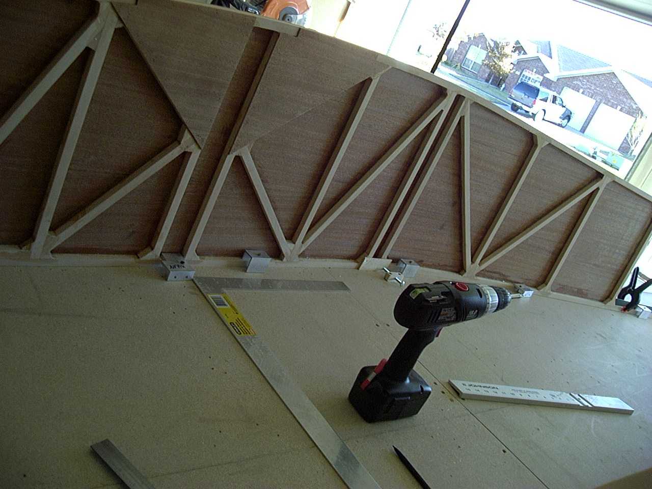
Once I had both sides done, before I could actually join them together, I decided to go ahead and put the
wing saddle gussets on.
Notice that I left room for the gussets on the cross members.
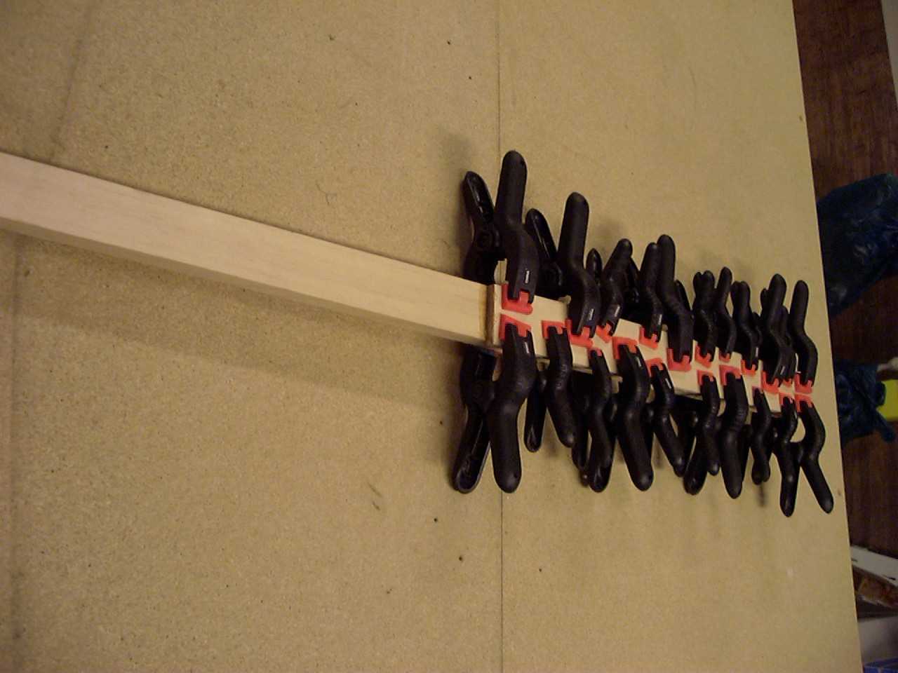
Part of the process of pulling the two sides together involves attaching the rear post of the vertical
stabilizer. Before you can do that, you have to laminate a piece of 1/4 inch plywood to the lower half of it as seen here
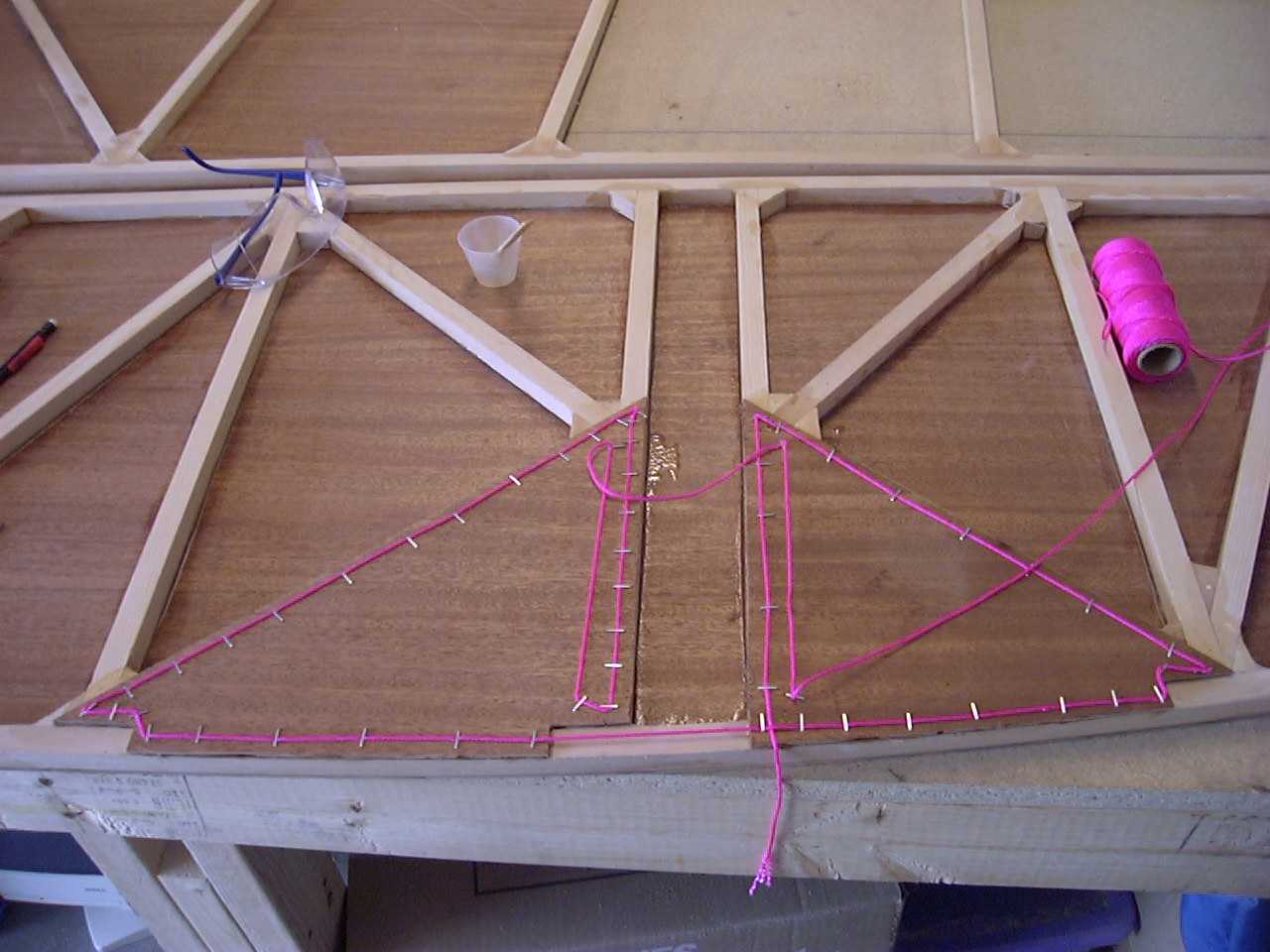
I then drew out the outline of the top of my plane on the table top and used some aluminum angle to act as a
jig for the table.
This ended up being a little to "aggressive" when it came to bending the sides of the boat. I was originally going to go
with an additional six inches in width. The problem I came into was trying to bend the sides. I ended up with a not so
pleasant sound coming from one of my longerons. (see the Oops! section for more info)
So I went back to the drawing table (literally the drawing on the table) and figured out how to make it right. This
time I went with four inches over stock and tried not to make the bends so sharp. This worked out well.
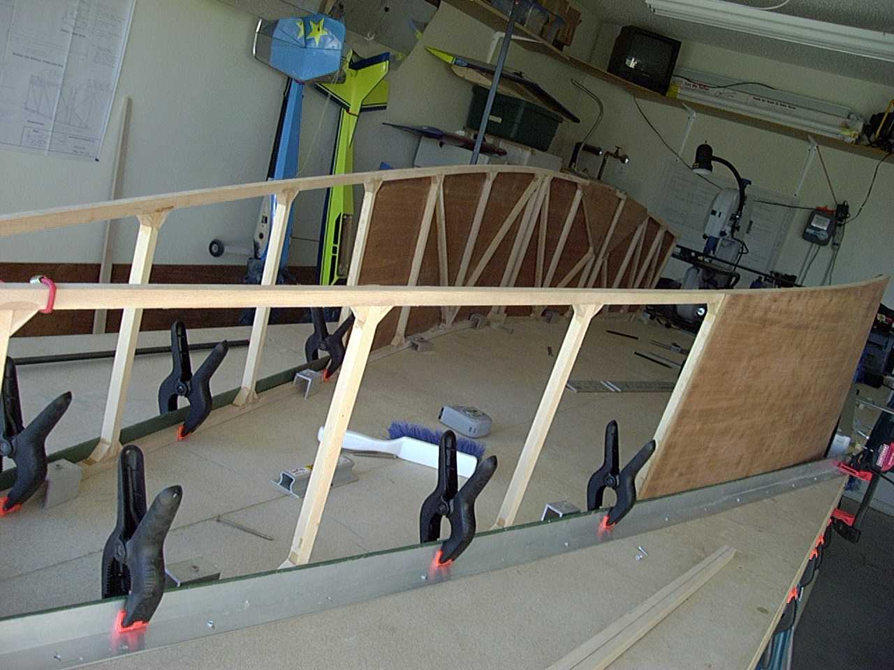
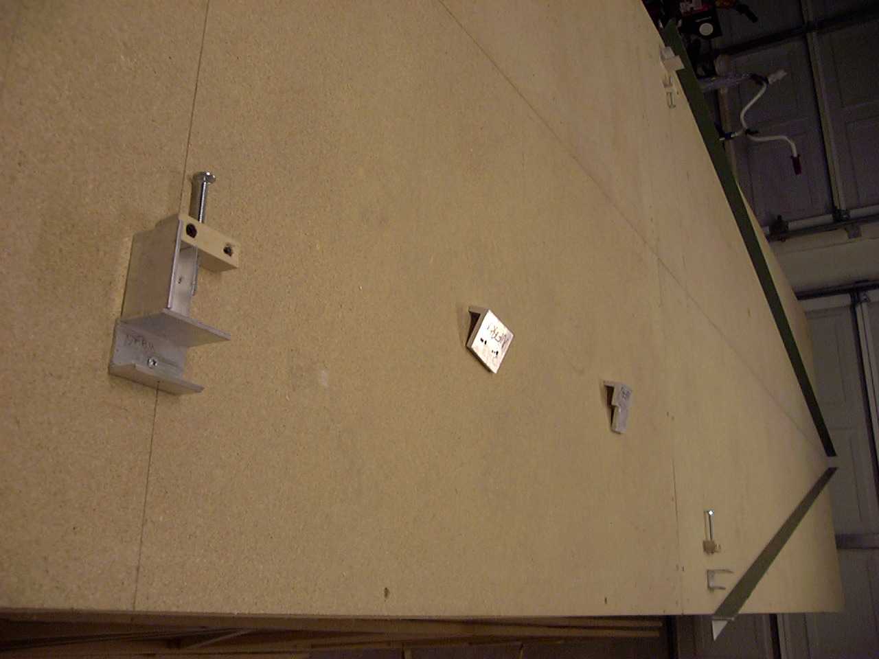
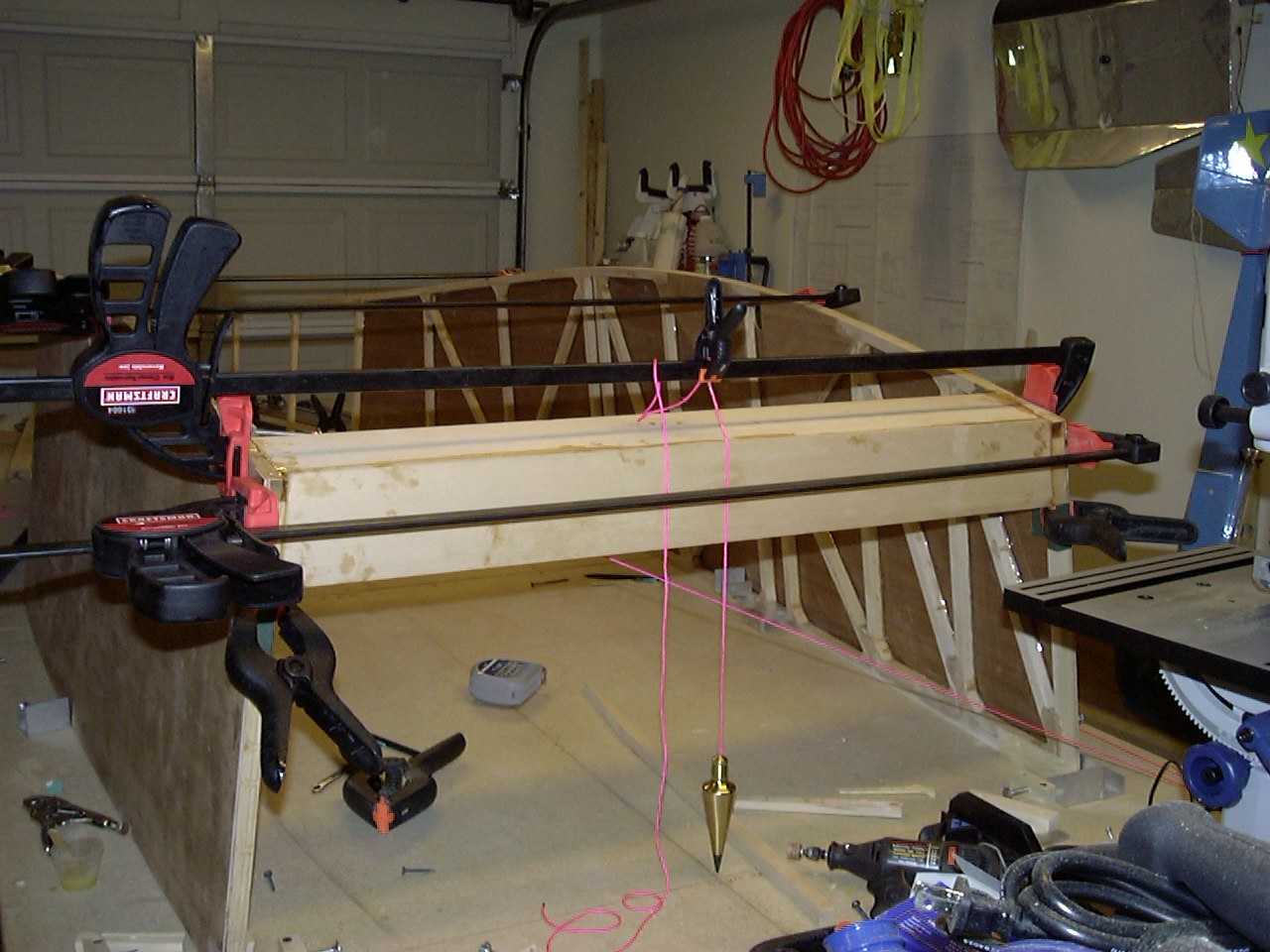
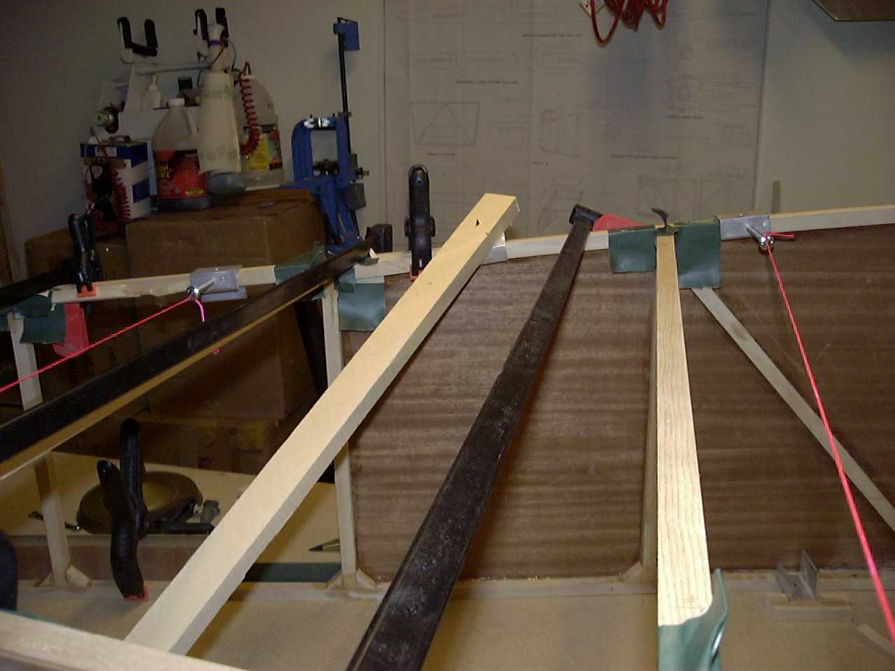
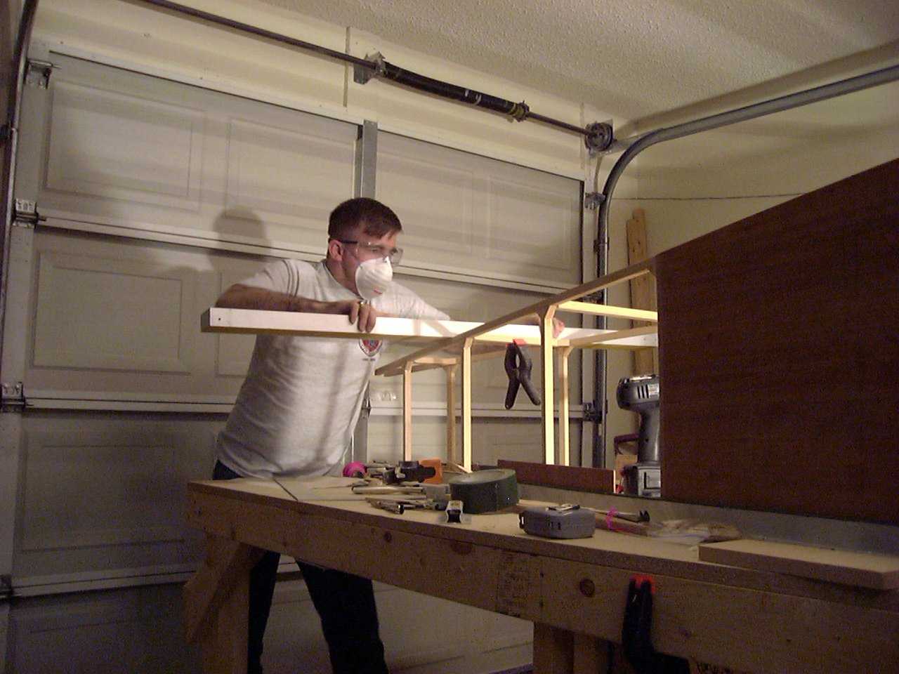
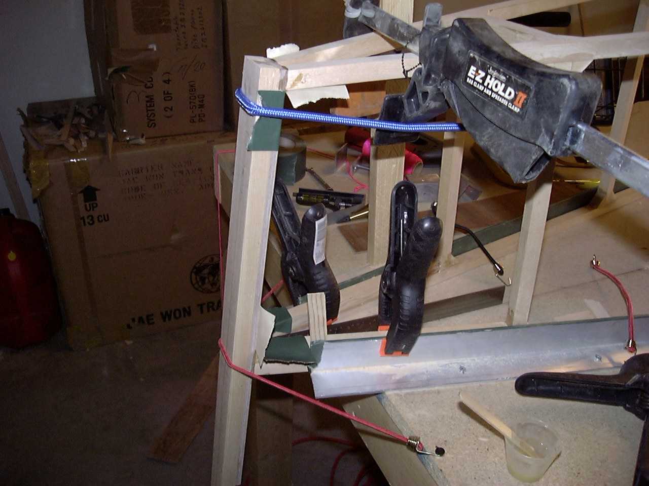
Now that the sides are framed onto the bench, it's time to start connecting the two sides together. I started
with the lower firewall brace and firewall compression brace. As you do this, make sure to keep the center of the brace
is directly over the center of the table. You will note here that there is a plumb bob hanging from the clamp. It
touches the firewall brace at its center and the point touches the centerline drawn on the table.
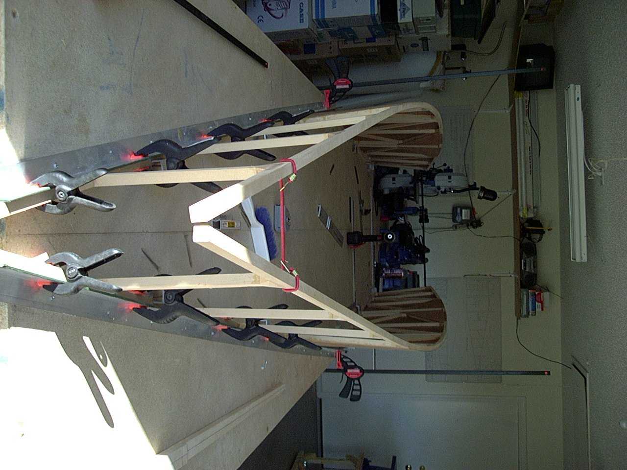
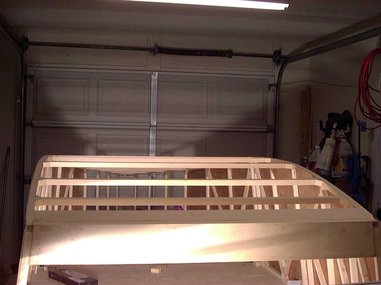
From there, I just went on back and added each cross member (again taking care to line their centers up with the centerline drawn
on the table). Note the duct tape to keep epoxy off area's that will later have gusset blocks glued in place.
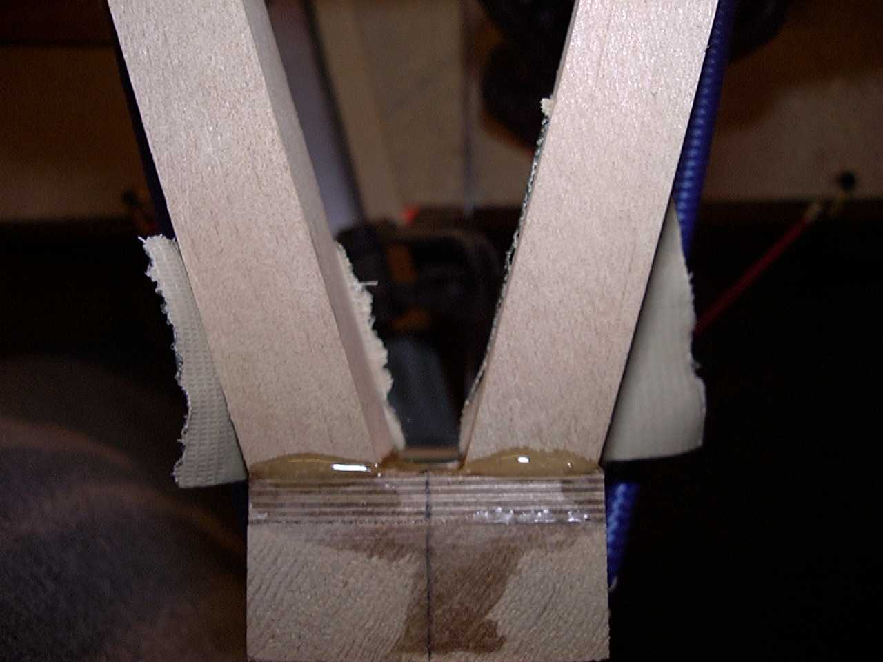
Once all the cross members were in place, the duct tape was removed and the gusset blocks were glued in place. I
coated them with epoxy, put them in place and held them there with mixing sticks and clamps.
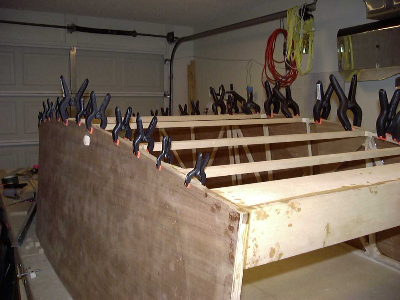
A little sanding after the epoxy dries...
and we have...
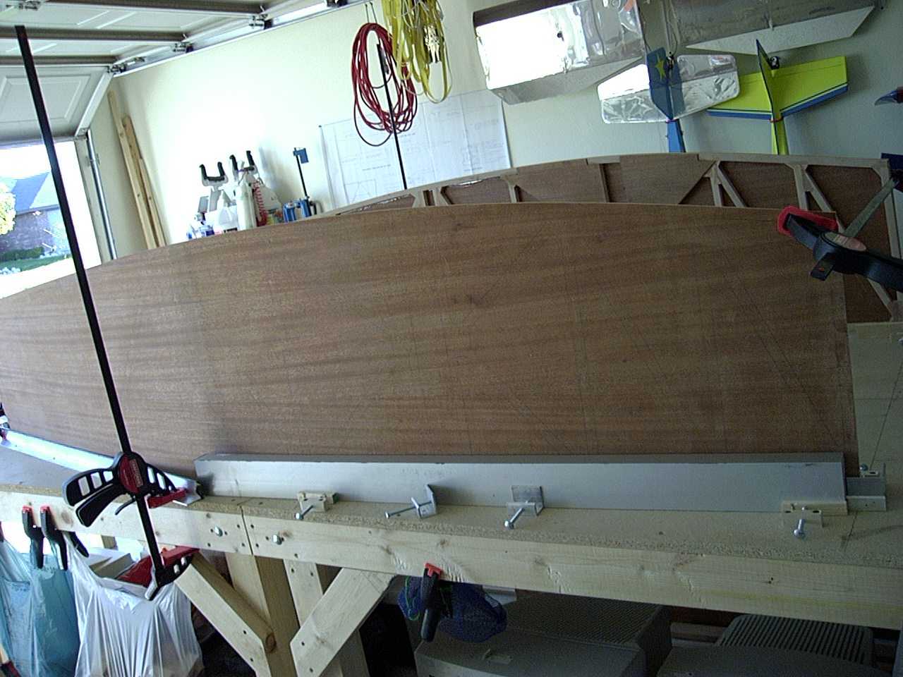
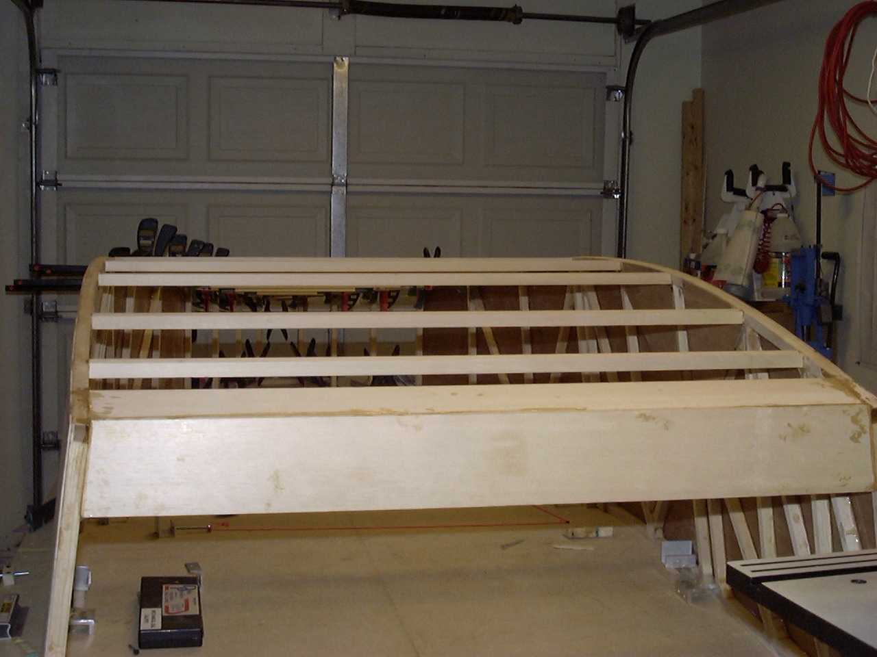
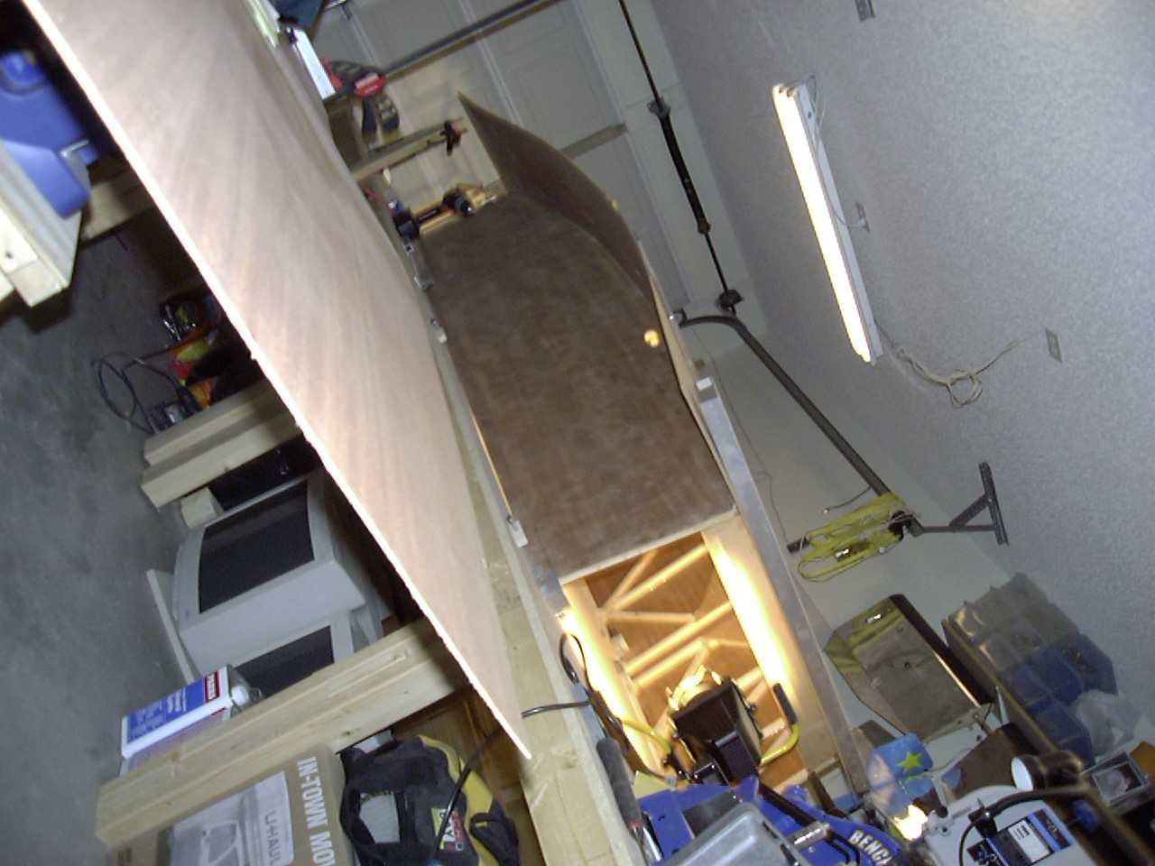
The next step is to sheet the bottom of the boat with a very large plywood gusset...the bottom skin!
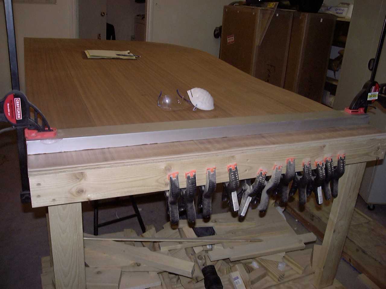
Make sure you design out how you are going to use those sheets of plywood. If you order the plywood kit from Wicks like I did,
you will only get three sheets of 4'X8' mahogany plywood (you don't want to have to buy anymore than that because it is
expensive!). You want to make sure that you don't cut up any parts that you need. You will use one full sheet to sheet the bottom
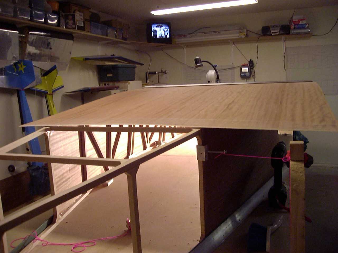
and then a part of a second sheet to finish it off. Here you will see the first full sheet on the boat (not yet trimmed
to fit) and the second sheet scarfed and ready to be cut to size.
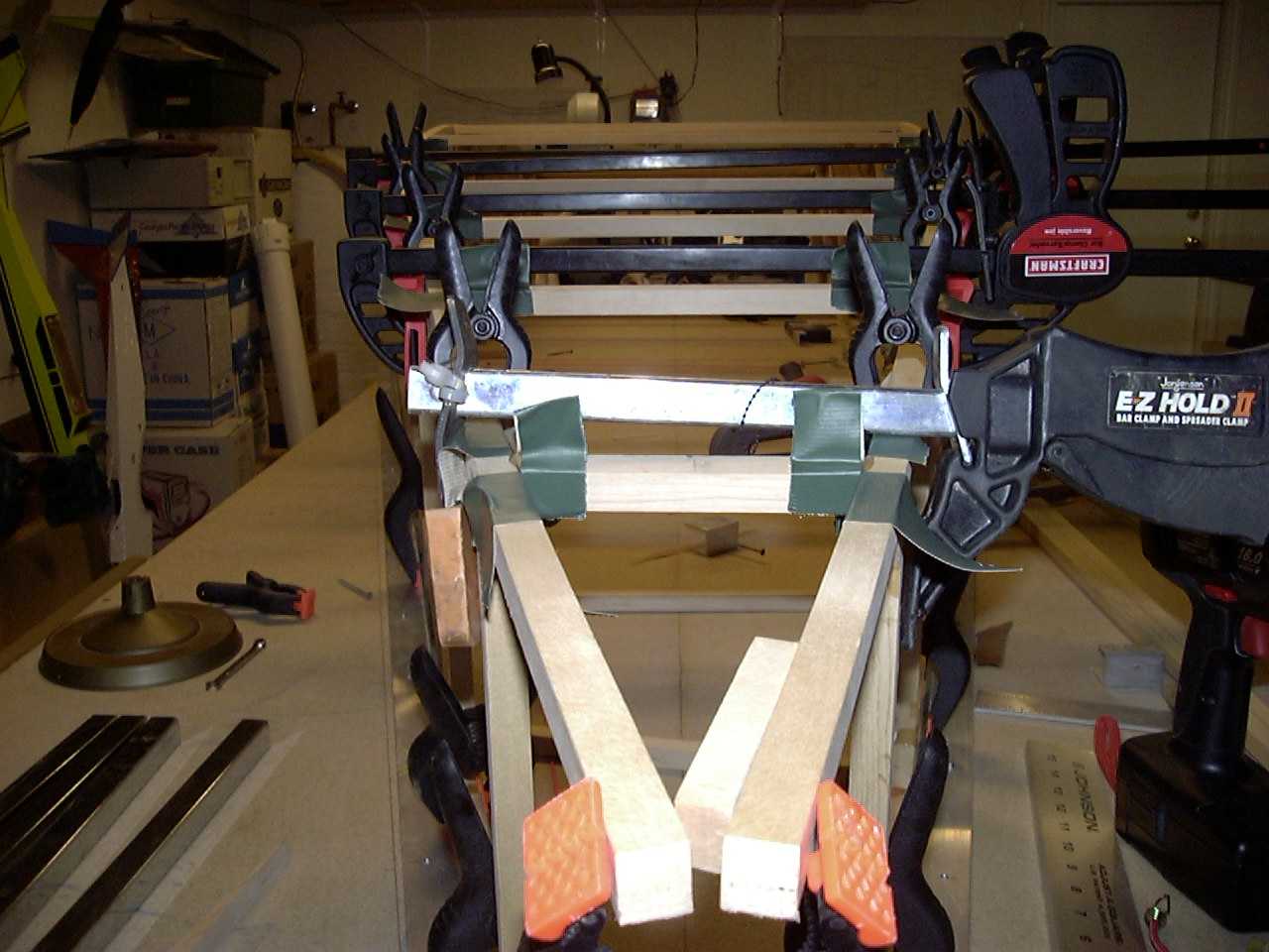
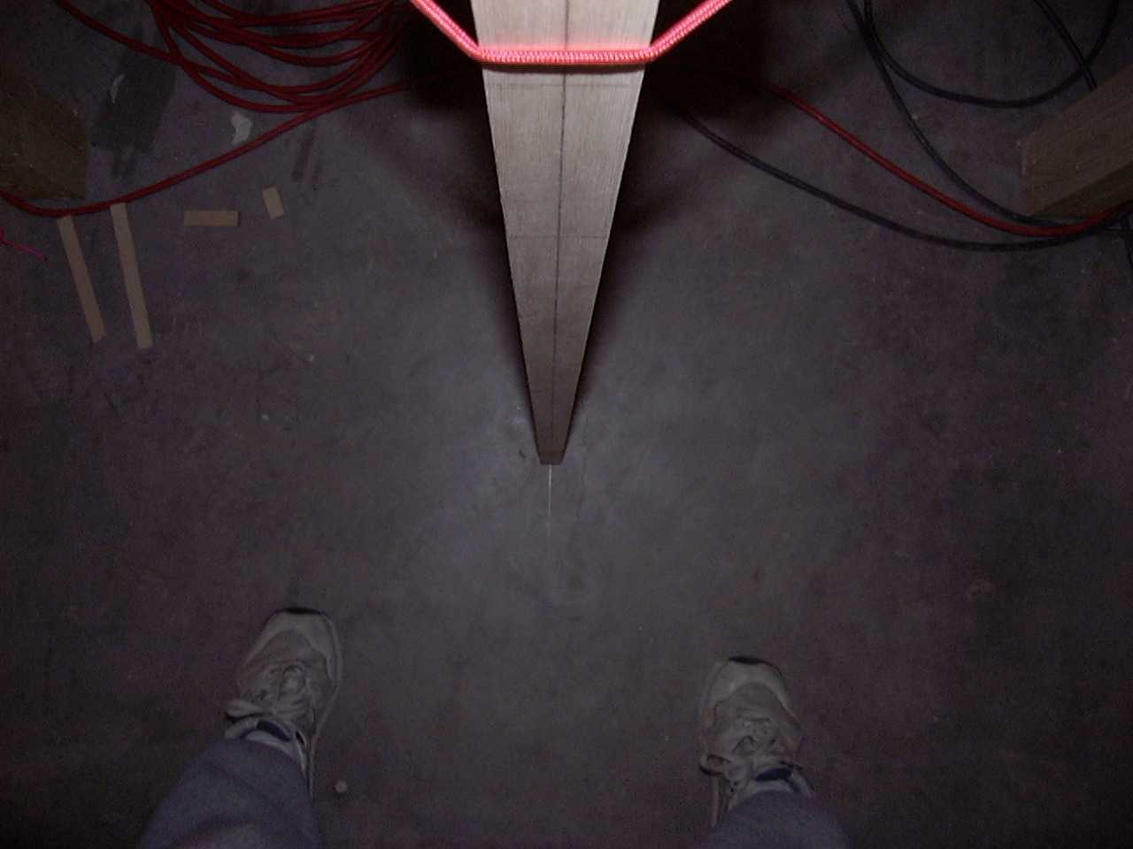
Before you can put the bottom sheet on, you have to attach the rear tailpost for the vertical stabilizer. Make sure that
everything is "square".
Notice the excess epoxy. I have no doubt that there is enough between the parts.
I really should have done some more work on getting the angles all down. I have a feeling this is going to be a real
pain when it comes down to getting this to the right shape.
Back to Fuselage Page 1
On to the next Fuselage page
Back to main page