15 June, 2005
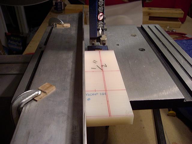
The plan with the rudder peddles is to use 5/8 inch, 0.049, 4130 steel tubing. I plan to use nylon blocks as bearings.
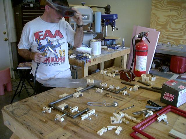
Here the nylon block is marked and ready to be cut into smaller blocks.
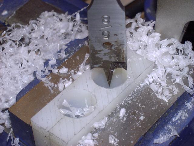
A spade bit works great to drill the holes (here two blocks are held together and drilled). These
are the second set I've made; the first set turned out ok, however, I had the drill press speed to
fast and some of the holes were "melted" into the block rather than drilled.
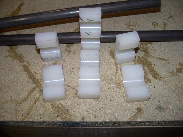
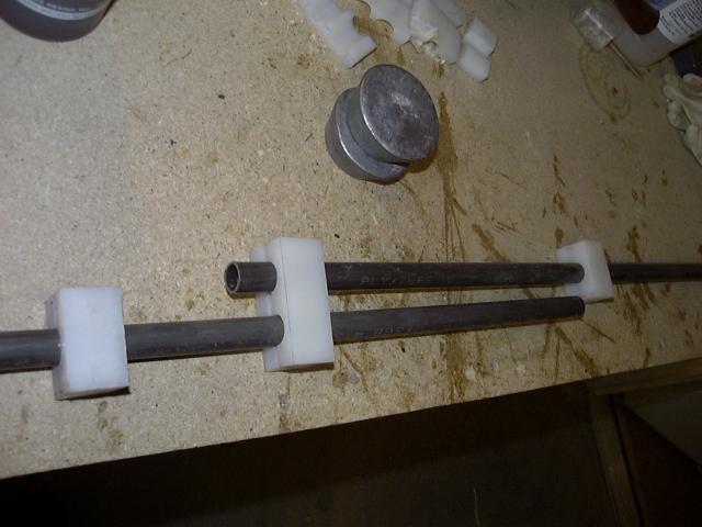
Ready to test.
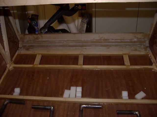
Small spruce blocks are glued to the fuselage floor to provide additional support (do this before
you lay down the plywood floor).
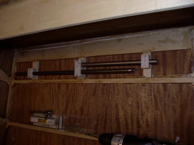
I forgot to take any pictures while I was welding up the rudder peddles, so here is one sitting on
the jig. These peddles are built per plans. Since my fuselage is wider than plans, I've discovered
the peddles are not wide enough. I'll be making a second set soon and will make them wider and a
little taller to accommodate the brake hardware.
2 July, 2005
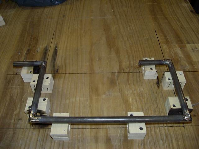
This update is for the second set of rudder peddles. Here I have the first one set up in the jig ready
to tack weld together. You can see my clamps I made to jig the fuselage--its a good thing I never throw
anything away!
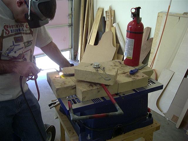
Once I tack welded the first one, I removed it from the jig and put the second set in the jig and tack welded
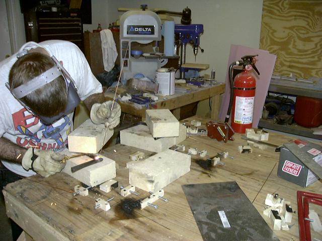
it. After they were both tack welded, I brought out the firebrick and proceded to finish weld both sets. The
firebrick is holding the whole thing down to minimize warping.
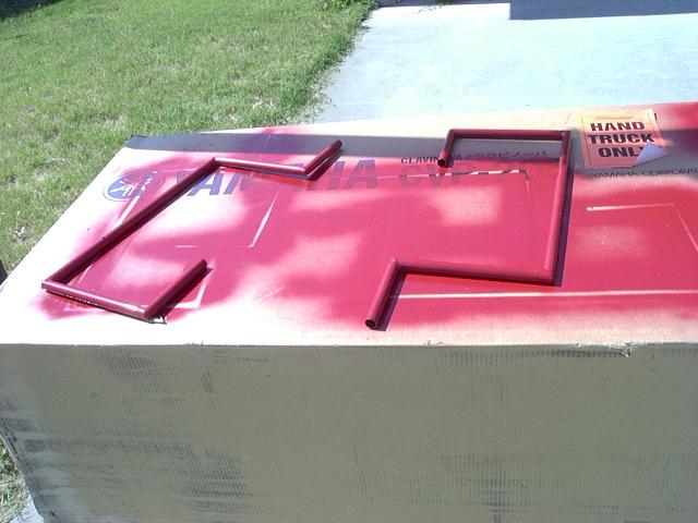
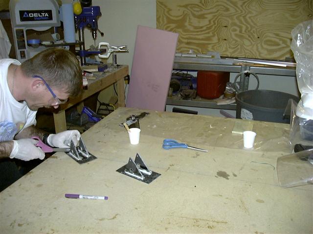
After cleaning up the welds, I painted them.
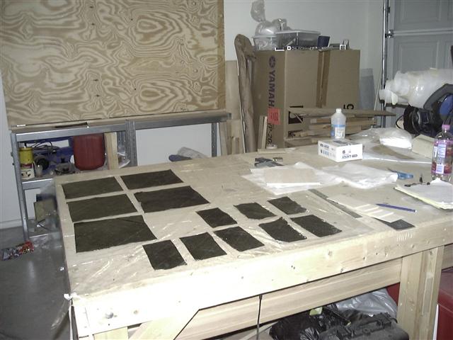
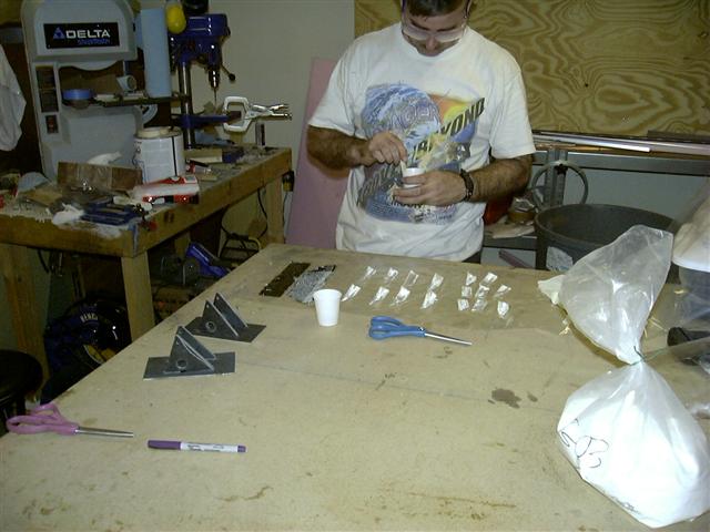
The plan of attack for the rudder peddles is to use carbon fiber. In this photo, you can see some of the pieces
as I'm laying them up. The five large pieces will be used to create the hinges for the canopy (I hope) and the eight
smaller pieces are the ones I've used for the rudder peddle assemblies. You can see a few of the pieces of balsa wood
to the right of the layups as well as a test piece I made earlier. The pedel itself is made of one piece of 3/32 inch 3X6
inch balsa wood with a layer of carbon fiber on each side. The mounting pieces are made of three pieces of carbon
fiber with two pieces of balsa sandwitched between.
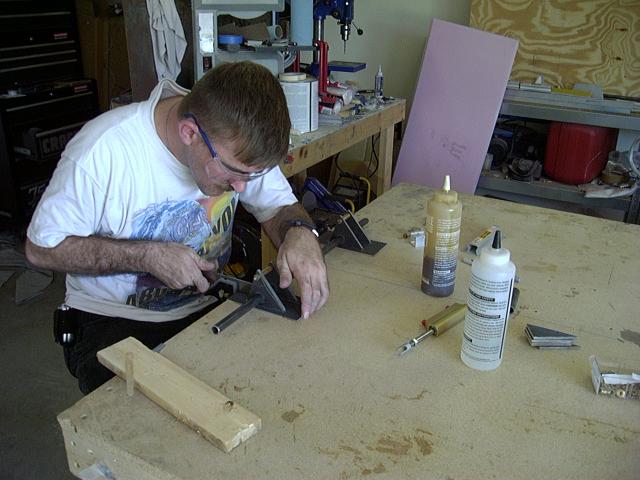
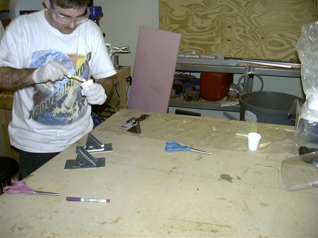
Here I am gluing the pivot braces to the peddle. I am applying glue to the mounting surface. This is only the first
step--once it it dry, I'll go back and add a piece of fiberglass or carbon fiber tape around the edges.
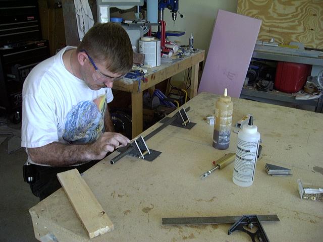
Here I am making sure everything is straight. The mounting bolt for the brake cylinder is being used to keep the supports
together. I've used washers in between the two pivot braces in this picture.
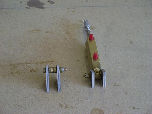
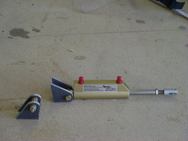
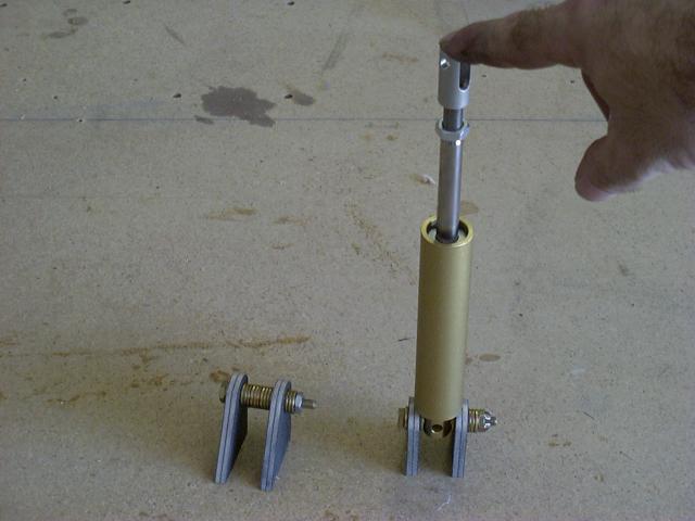
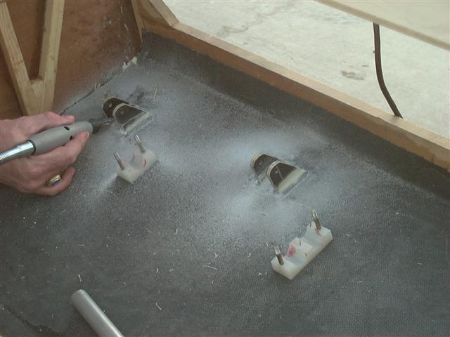
Here is an example of the bottom pivot braces. These three pictures show what they will look like when installed.
Here I am installing the lower pivot braces in the fuselage.
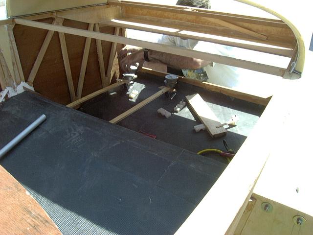
Because of the way the lower pivot braces are cut, they did not want to stay upright when glued to the floor of the
fuselage once I put the weights on to hold them down. I had to result to the "Mark I Leveling Device" (aka trashcan) to
make the angle more agreeable.
These next three pictures show me preparing the fiberglass tape to reinforce the upper and lower pivot braces, floxing the
radius of the upper pivot brace, and finally trimming the fiberglass tape on the upper pivot brace.
8 July, 2007
After talking with Bill Clapp at Oshkosh a few years ago, he recommended adding a corner gusset to each corner on the rudder
peddels. I took his advice and added the gussets.
Here I have attached the brackets for the break cylinders to the floor and I'm cleaning up the excess glass.
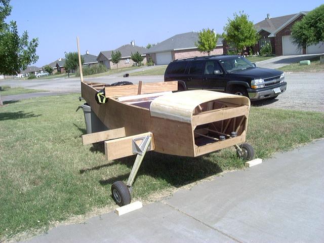
I then dry fit everything to see how the geometry works. I've still got to play with it a little, but this will work for now.
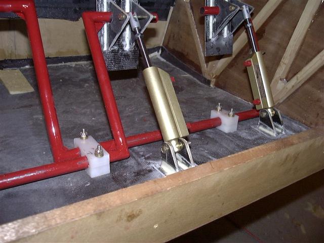
More to follow!
Back to main page