19 April, 2003
Here are a few things I have done so far for my control system. I'd like to get as much of it fabricated as I can before I actually have to put it in the airplane. The first parts I attempted to fabricate were the aileron bell cranks. Here is the CAD plot prior to being spray glued to the aluminum rectangular tube (1"X2" 6061-T6 aluminum). You may note that this will create two identical parts. I was trying to "save" aluminum. I figured if I could nest the two parts, I would not have to use the whole 12 inches of the tube. Not only did this cause great consternation later, but proved to be a real pain when I was actually trying to cut the parts out on the bandsaw. Lucky for me that by "nesting" these two parts so close, I had enough metal left over to make the second side the correct way. These parts were cut out using a bandsaw with a metal cutting blade (lots of teeth). This worked, but was a VERY slow process.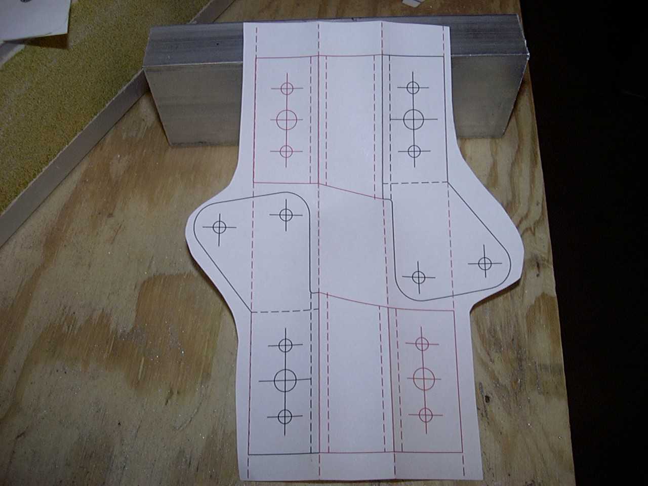
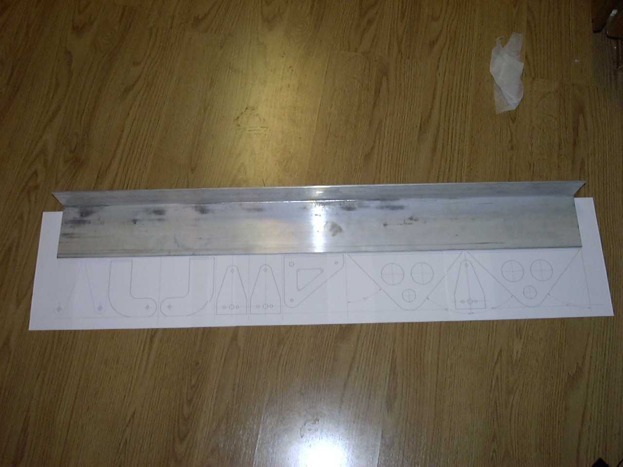
The next series of parts I decided to cut out were all of the parts made from a piece of 36 inch long
2.5"X4" rectangle (6061-T6). Out of this piece, I made: (2) control stick mounting brackets; (2)
upper bell crank support brackets; (2) lower bell crank support brackets; (2) upper bell crank arms;
and (1) bracket for my elevator counterbalance bracket. To rough cut these parts, I used my chop
saw with a metal cutting blade. This was not much faster than the bandsaw with the metal cutting
blade. Another thing I noticed when making these parts is that this piece of angle was not 90
degrees. The angle is only about 80 to 85 degrees so I'm hoping that this does not cause me some
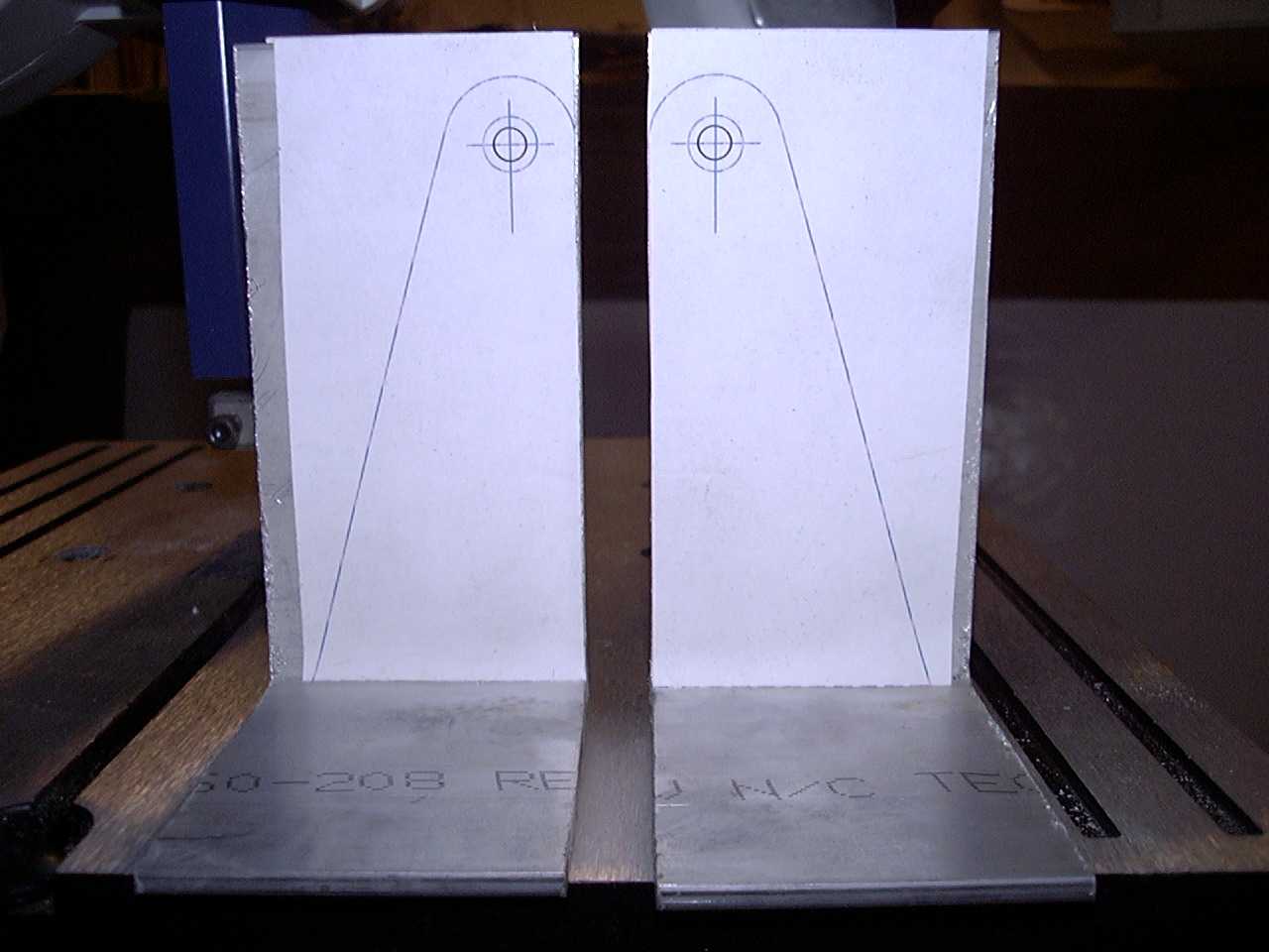
problems in the long run. This first picture shows the original plot on how I had planned to lay out
the parts.
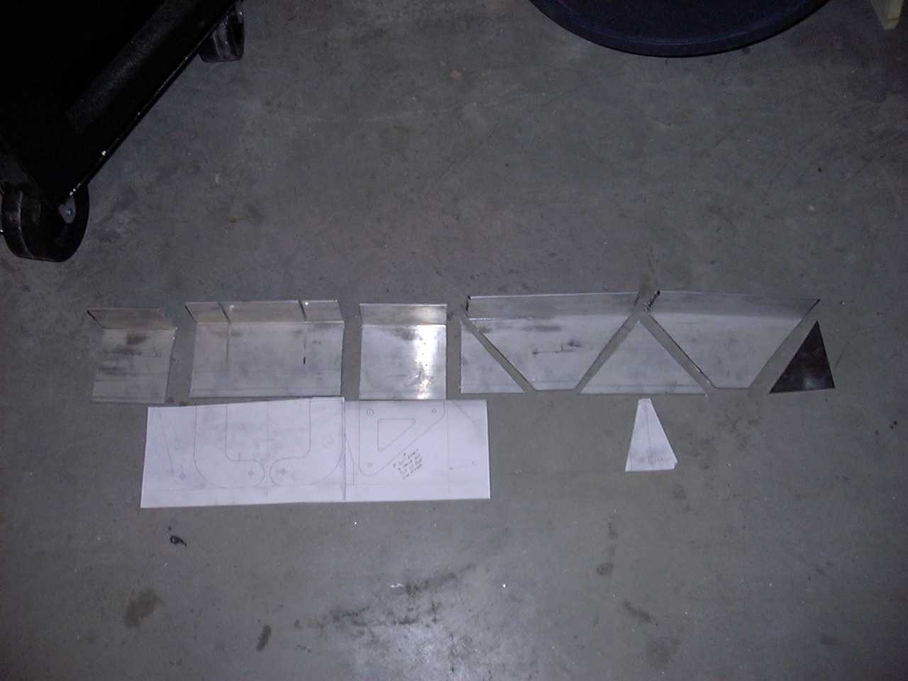
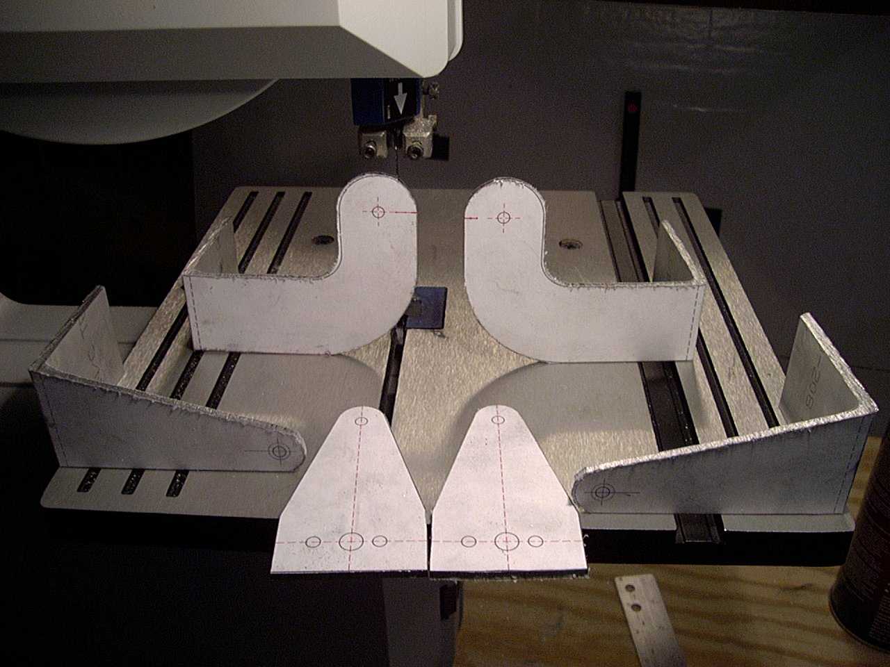
This one shows the parts rough cut in the way I ended up using them. You'll notice that I decided
not to cut the upper bell crank arms out of its section of the angle. Instead I decided that I
had plenty of aluminum between the two lower bell crank support brackets (second picture). Notice
also that the second picture shows how I cut through the vertical piece of aluminum of the angle with
the chop saw. This is because when I was cutting out the lower bell crank arms out of the 1"X2"
tube, the bandsaw had a real hard time cutting along the 1 inch side (took FOREVER!). This was my
attempt to "speed up the process".
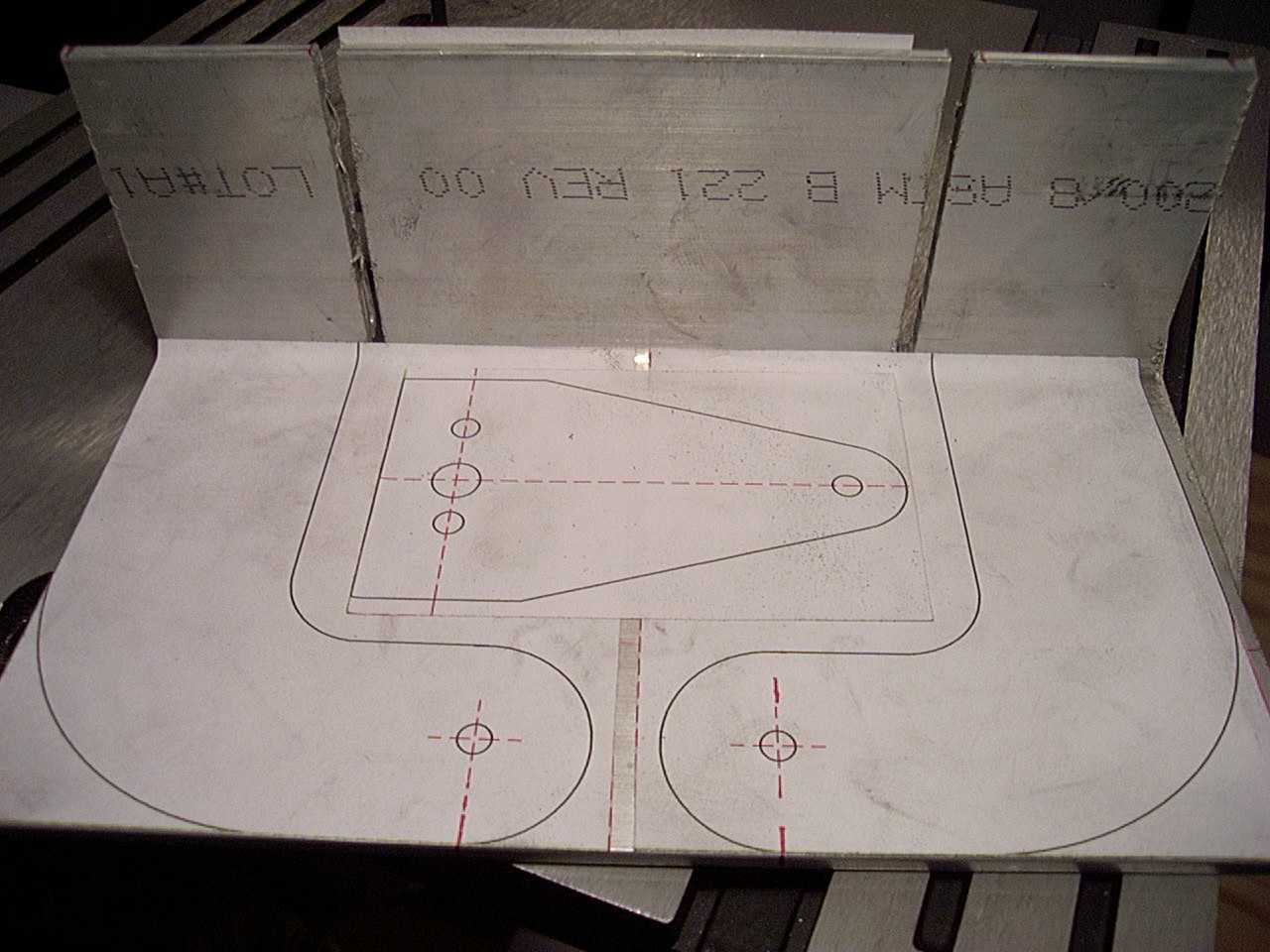
I contemplated trying to see how close I could get the angle on the chop saw to cut out the upper bell
crank support brackets and finally decided to try the bandsaw again. Since my metal cutting blade
was almost broken (cracked about half way through in one spot), I decided to replace it. I had heard
somewhere that a woodcutting blade would cut aluminum so I decided to give that a try before burning
up another metal cutting blade. I am now firmly convinced this is the right way to go. With a
woodcutting blade, the bandsaw chews through the aluminum like it was butter (almost too easily!)
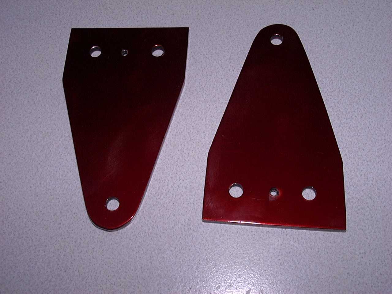
Here are the before and after shots of some of the bell crank parts.
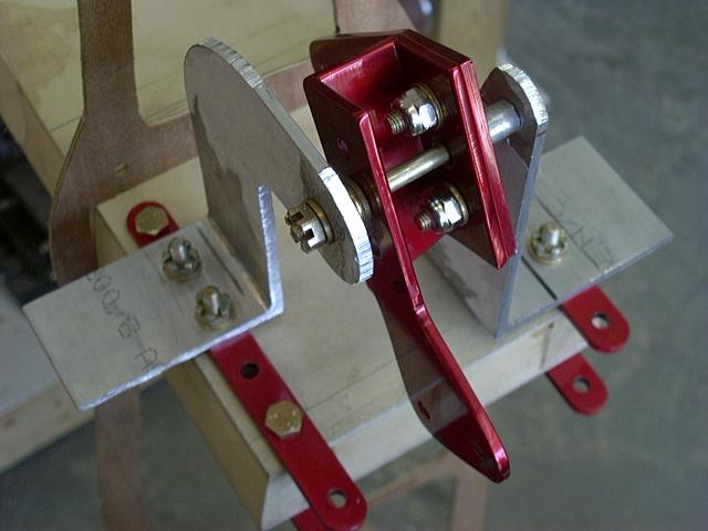
Here are the final aileron bell crank parts after they have been anodized (see the
Corrosion Control section for more information on the anodizing process).
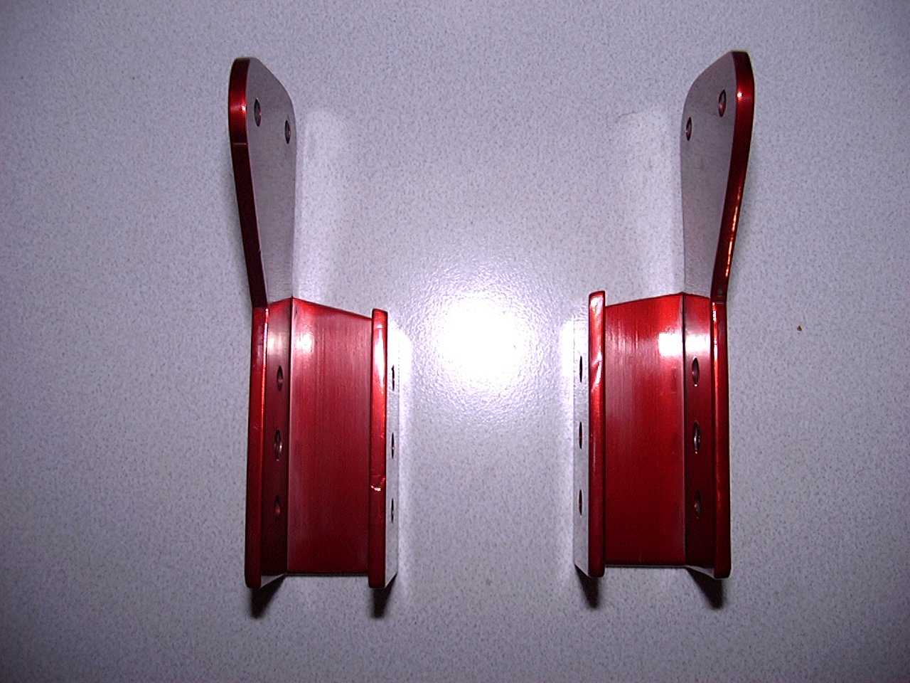
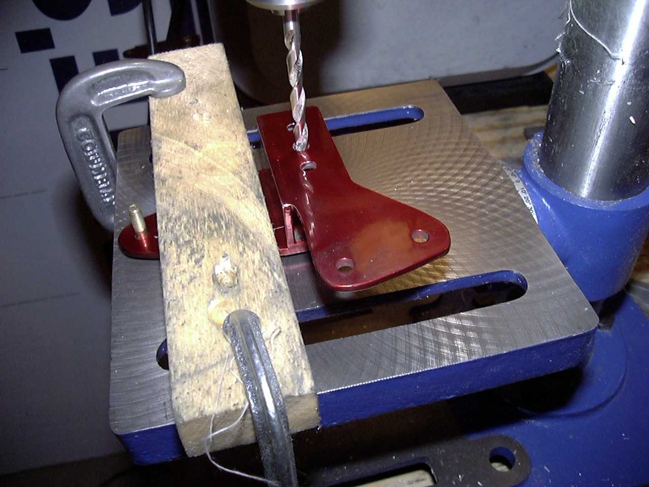
The third picture shows how I drilled the final hole for the pivot bushing after I had bolted the two
parts together. The bolt in the third hole of the bell crank upper arm is there to balance the part
since there is already two bolts holding the bell crank lower arm on.
15 June, 2005
Here is a quick update with the aileron control bellcranks. I've actually made more progress than I have pictures for at this time, so look for more to follow.
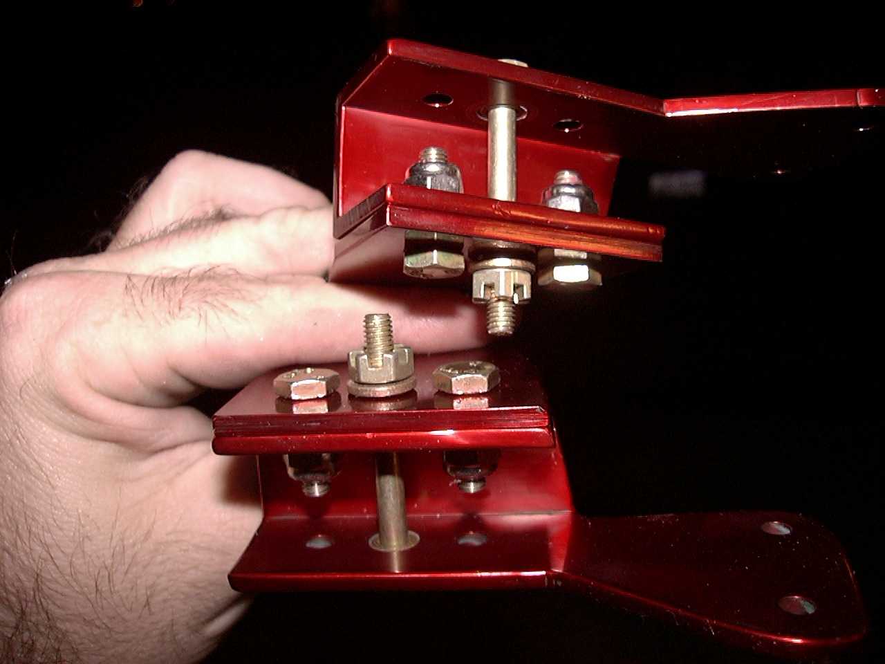
This shows how I "jigged" both bellcrank brackets up to ensure the bolt hole was centered in both.
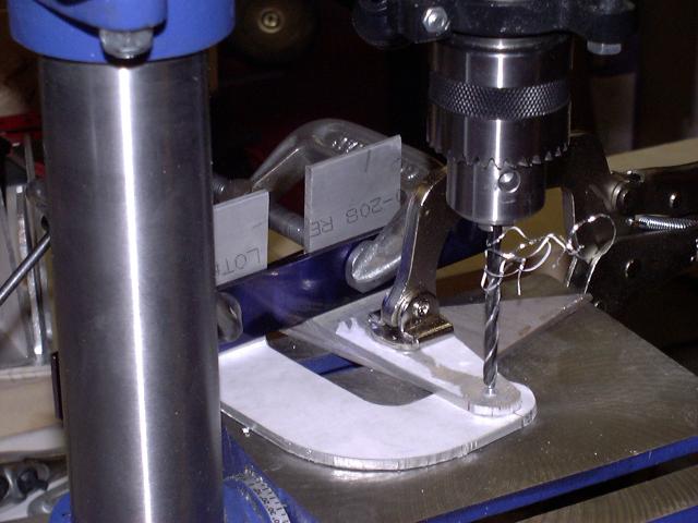
Here I am working out the best location to drill the holes to mount the bellcrank brackets to the
rear spar.
All bolted up and ready to trim. The next step (not shown here) was to trim the Aluminum angles,
clean them up and anodize them.
16 June, 2005
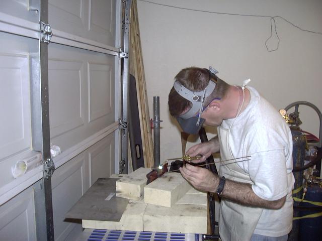
This update is for my duel control stick assembly. I am using the same basic setup that Mark L.
is using with one exception; I am using a 1 inch diameter center tube. Here I am tack welding one
of the two washers on that will be bearing surfaces. I will say that I found it easier to weld the
thicker material to the thin material than I did two thin pieces together.
Once the two washers were welded in place, I built a simple jig to hold everything together while
I tack welded it. I then took it off the jig and finished welding the joints.
I did find out that welding aluminum is different from 4130. After several practice pieces, I
figured I could get the job done, however, I decided why weld when you don't have to. Instead,
I cut a notch out of both sides of the .75 inch AL tube where the controls hook up. This saved
having to weld the tabs on and the end result looks better. I started by drilling the pivot bolt
hole and the control cable attach hole in the AL tube. I then rotated the tube 90 degrees and cut
out a notch on both sides for the control cable connections to pass through (I'll get better pictures
later).
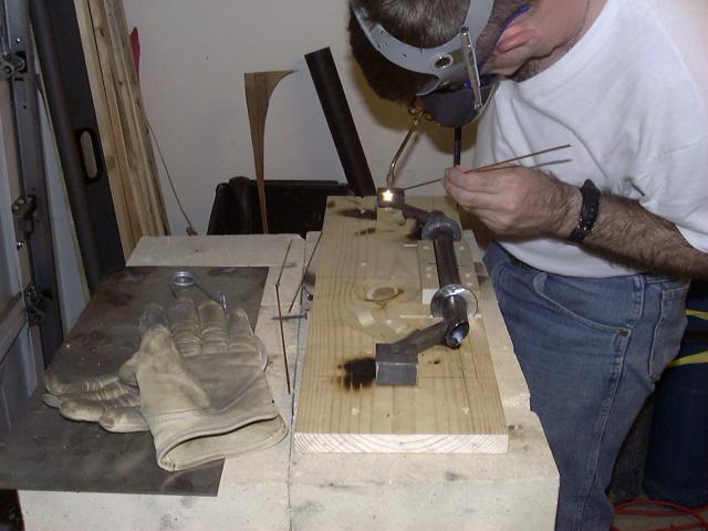
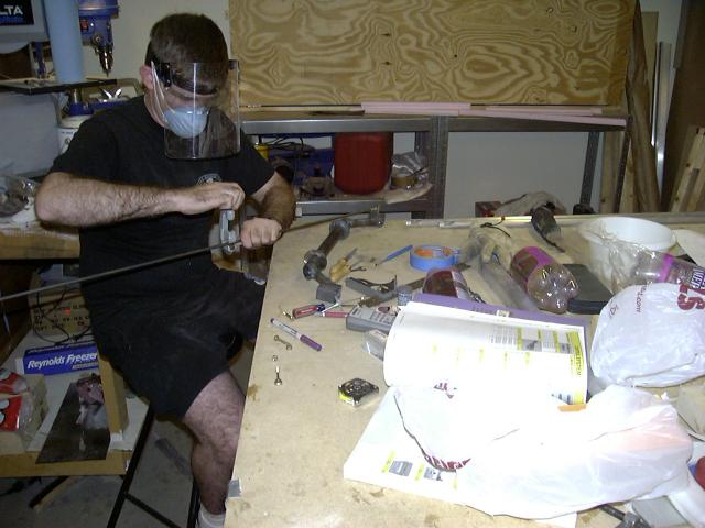
For the rod that passes through the stick assembly, I used a piece of 4130 tubing and tapped the
ends for an eye bolt (again, more pictures to follow). Here I am cutting the tubing to length.
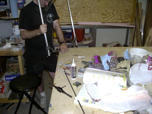
Here is a trial fit of all the pieces. I have not cut the sticks to the proper length yet.
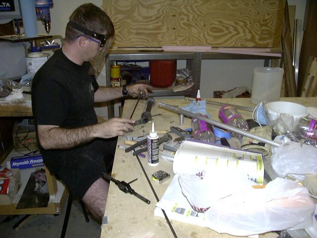
To make sure the rod was the right length, I used the stick pivot holes as guidance. Once I had
everything to the right length, I cleaned out the tap cutting fluid (again using good ol' acetone),
let it dry, and then used Locktite 620 on the eye bolts. I put a bolt through each eye bolt into the
pivots of the stick assembly to let it dry.
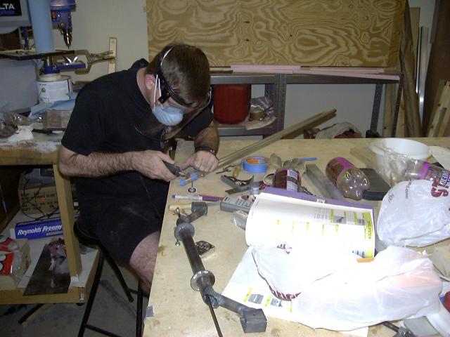
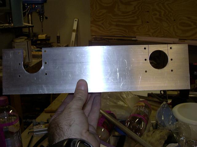
Next up is the mounting brackets. I cut out four pieces of nylon and drilled a single 3/16" hole
through the center of each. I then found where I wanted the center of the mounting bracket to be
and bolted the nylon blocks on, one on each side of each bracket. I then drilled and mounted the
nylon blocks using six #6 screws each. Once everything was lined up, I removed the screws and the
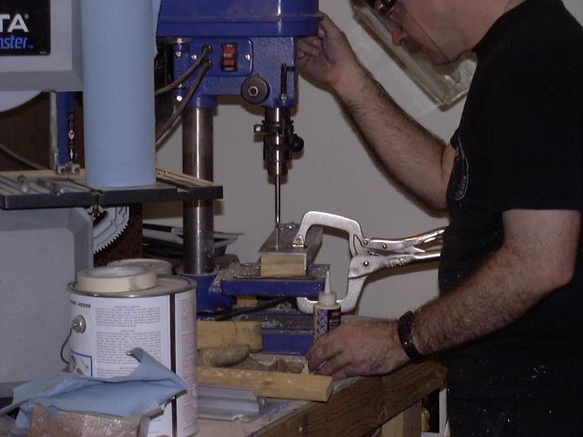
nylon blocks and mounted the bracket in the drill press to cut the holes where the stick will pass.
I used a 1 1/4 inch spade bit to "mill" the hole (the control stick is 1" in diameter, so this
provides clearance for the stick to rotate with no metal to metal contact).
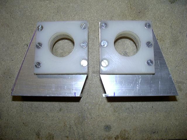
After both holes are drilled, I cut out the outside edge of the whole to allow the stick assembly to
slide in from the outside edge. Here one is rough cut and the other is waiting to be cut.
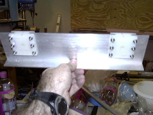
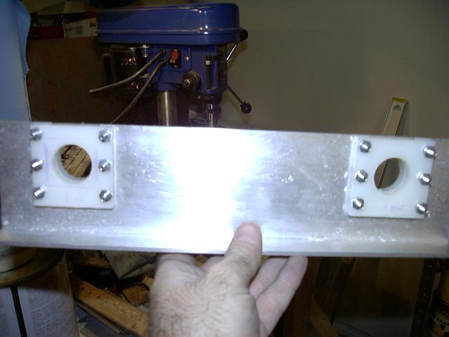
Here both brackets (one at either end of this piece of AL angle) have been trimmed and the nylon
blocks have been re-attached. You can see the original centering hole in both.
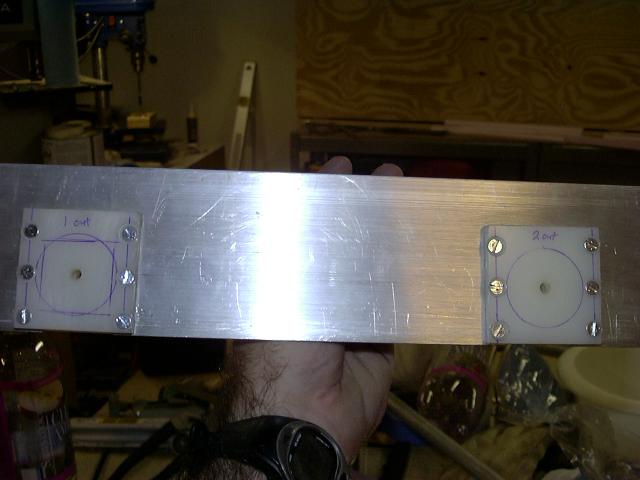
The other side showing a rough circle drawn to indicate the size of the hole drilled in the AL angle.
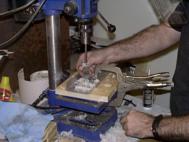
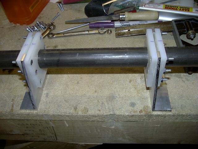
I then mounted the whole assembly in the drill press and drilled the nylon blocks. I used the center
hole to line everything up and drilled the holes with a one inch spade bit.
Holes drilled for both brackets.
Both brackets cut out (still need to be cleaned up).
Here they are on the bench with a piece of scrap tubing inserted as a mock up.
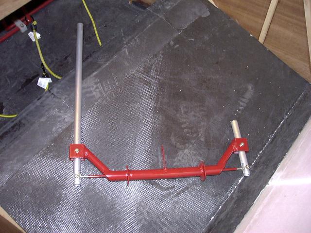
Letting the paint dry. In the foreground is the control stick assembly, and in the background
is the connecting rod.
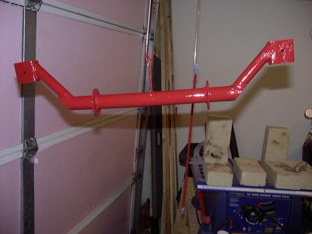
Here is the assembly with the connecting rod installed.
More to follow!
Back to main page