Back to main Corvair page
July 8, 2007
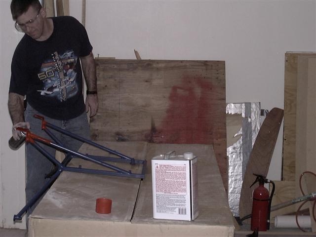
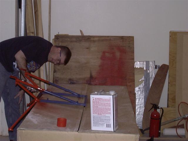
This is my engine mount as ordered from William Wynne. William sends everything painted blue so I have to repaint it to match my motor (Chevrolet Red-Orange).
April 26, 2008
Now that the motor is assembled, I need to work on all the "stuff" that completes it.
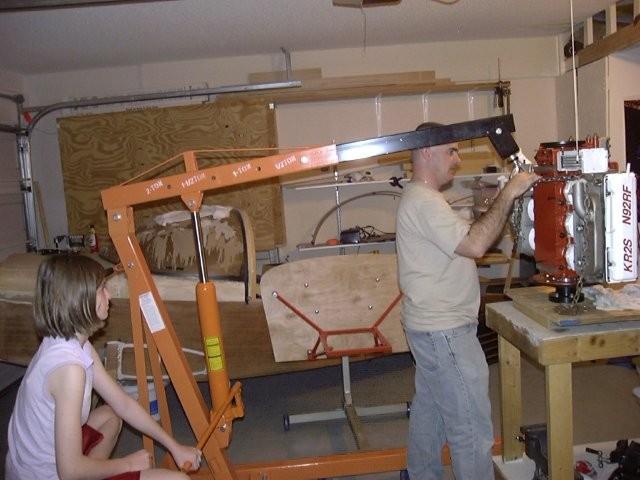
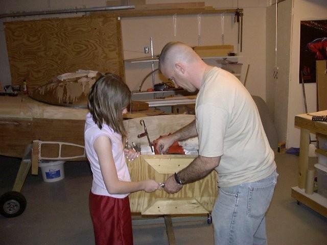
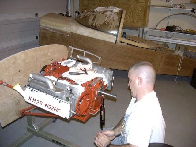
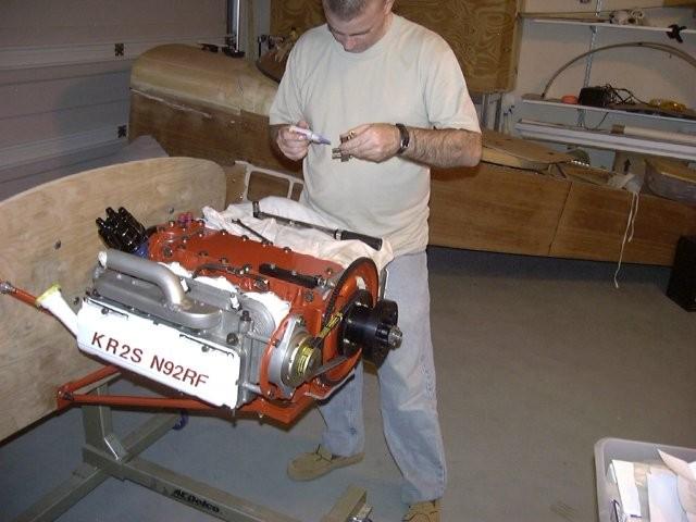
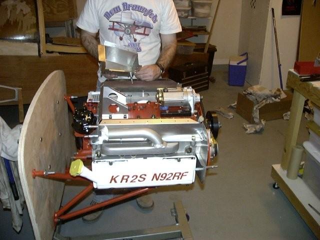
To start this, I need to get the motor off the assembly table an on its mount so
I can start putting all that "stuff" on. I've decided to build a "firewall forward
kit" by building a mock-up off the airplane. This way, I'll know where everything
needs to go when I comes to drilling holes in the real firewall. Here my (now 12)
daughter Miquela Hope is at the controlls of the cherry-picker as I hook the chain to
the motor so I can take it off the table.
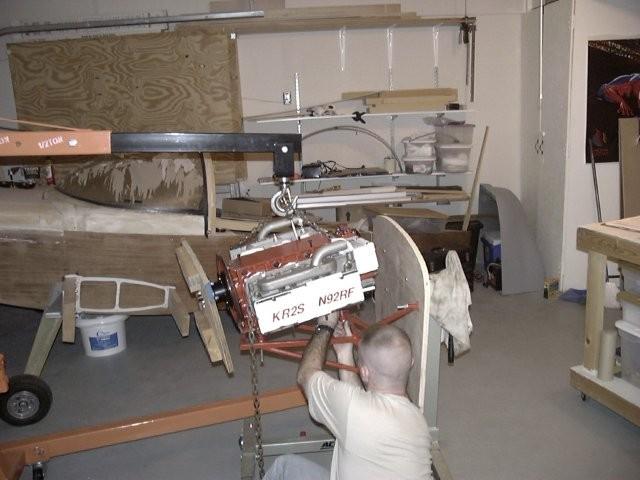
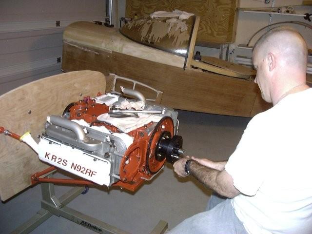
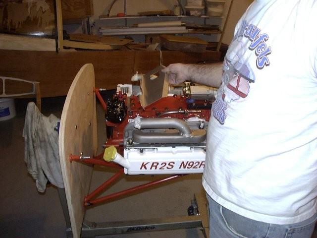
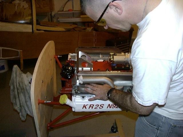
She is still at the controls as we put the motor on the mount. The mount is attached
to a piece of 3/4" plywood cut to the same shape as the airplanes firewall. It is
mounted on the motor stand so I can move it around. Don't forget to add the rubber
bushings or the motor will not fit (the oil pump will not clear the mount). I was only
able to get two of the bolts (one on each side) to point down, the others I had to put the
nut at the top.)
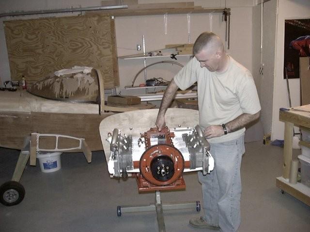
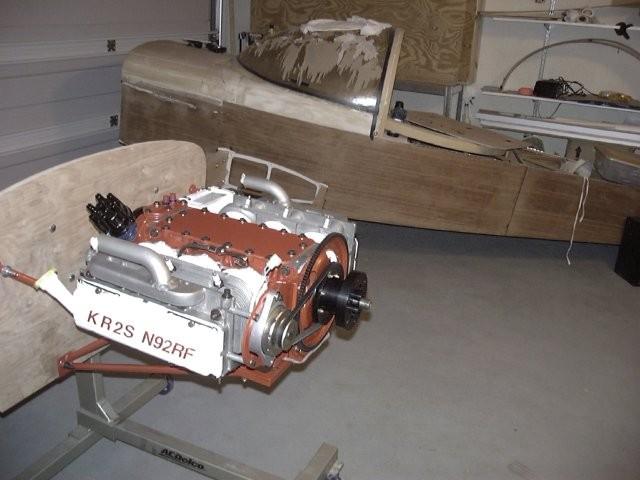
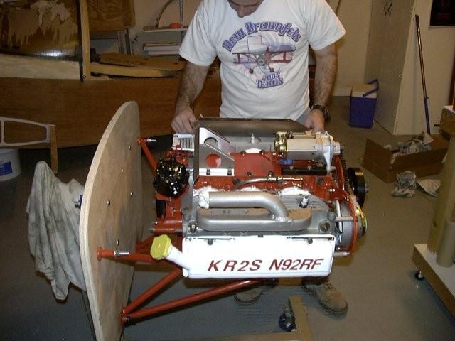
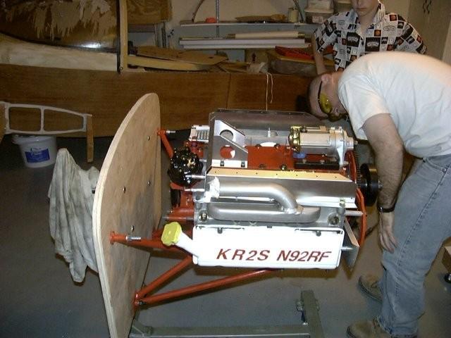
Miquela Hope helps to remove the plywood mount used in the assembly process.
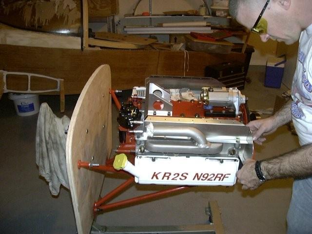
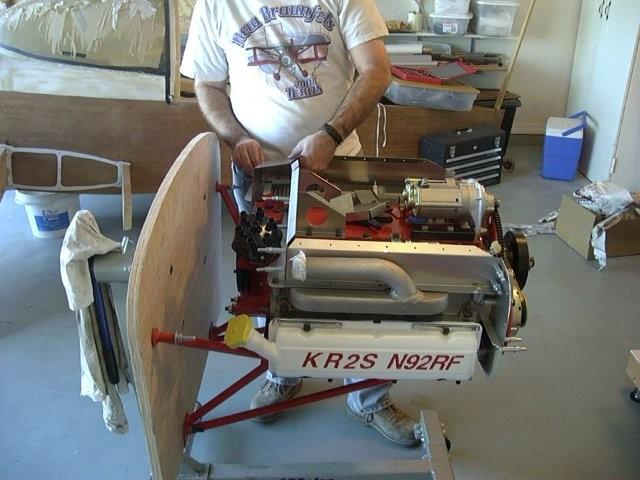
I put some bolts into the top cover knowing that some of them would have to come out again
as I put other systems in place.
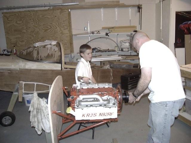
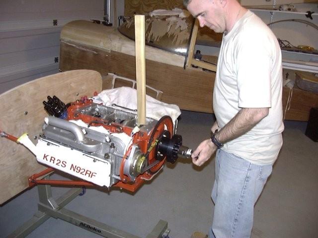
Ricky Lynn (now 11) "supervises" as I remove the prop hub for the last time to install the
alternator bracket.
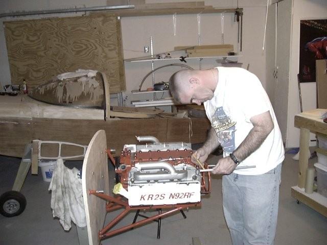
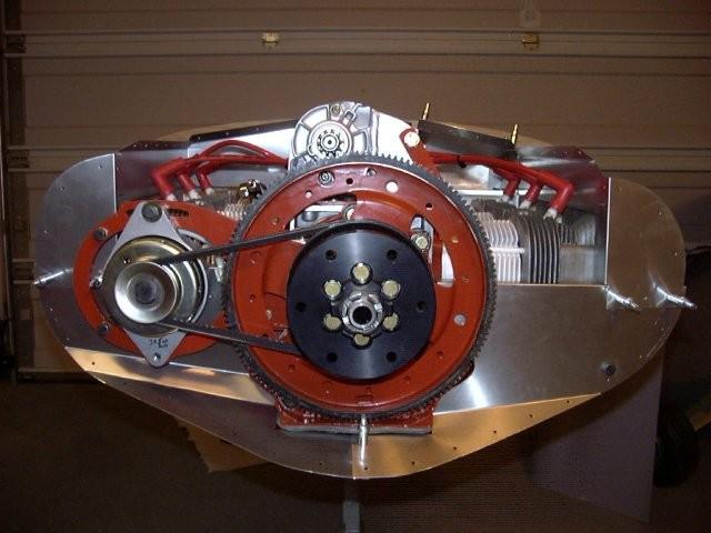
Once the prop hub was off, I put the alternator bracket back on. Here I am measuring to
create the stand-offs that keep the bracket at the proper distance from the heads. I
later had to alter these as I installed the baffles (see below).
Since I will not be able to get to these bolts again once the prop hub and ring gear goes
on, I decided to safety wire the bolts to keep them from coming loose (not that I think
they would, but I had already drilled the holes...)
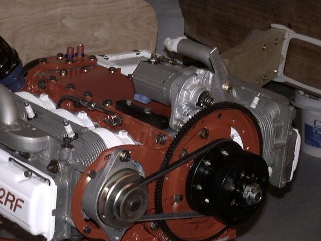
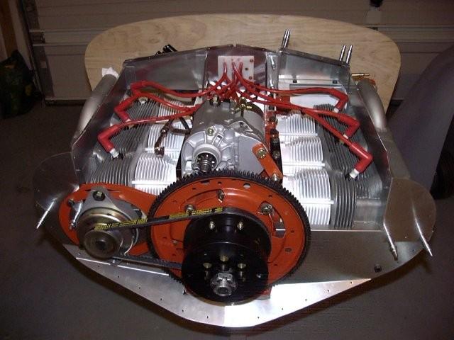
The prop hub and ring gear go on for the last time.
Alternator installed (so is the distributer).
Now to put the safety shaft nut on. I had to go buy a new socket to get it installed.
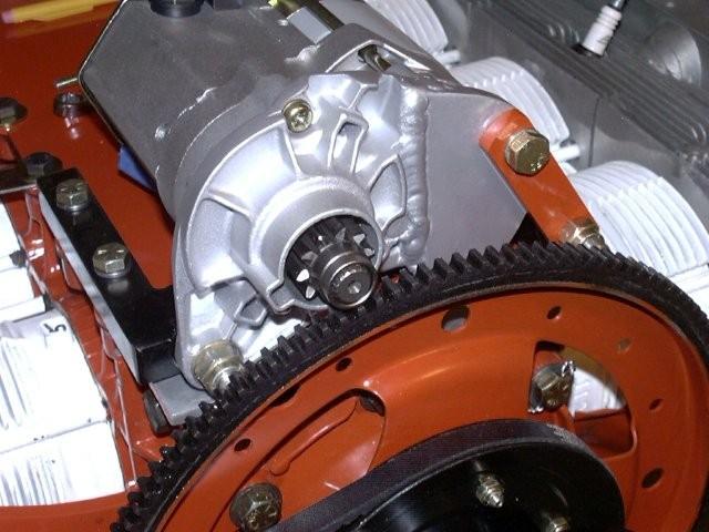
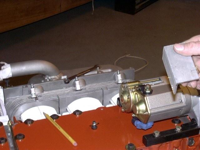
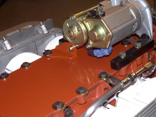
Now that I don't need to get inside the motor anymore, I put the top cover on with the
gasket installed. Here I'm in the process of putting locktite on the bolts for the
starter bracket. If I were to do it again, I'd wait to put the locktite on until you
have the starter brackets all finished. The bolts welded to the brackets are long
enought that you can't remove the nuts because of the ring gear. I had to remove the
brackets a couple of times as I was building the braces.
Here is the front bar bracket drilled and installed (before trimming and after).
Here is the tail bracket before it is drilled and installed and after.
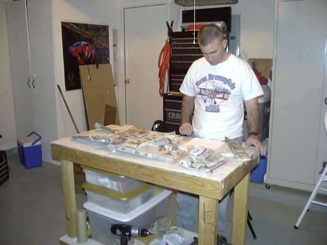
Now on to the baffles. I purchased the baffle kit from William Wynne and this is how
it comes. The main kit has nine pieces and then it has a sub-kit with four additional
pieces based upon which oil cooler you have. I think I was missing a page of the
instructions, because when I came to install the oil cooler, the only one it talked about
was the high volume oil cooler (it was like the stock coolers were mentioned on the next
page.)
You start the installation with the back piece. You have to drill one hole where it
mounts to the head. The pre-drilled hole mounts in the bolt-hole located between the
top cover and the remote oil filter bracket.
Each of the two verticle braces use two bolts from the top cover to keep them in place.
You have to drill all holes in these brackets. They also get drilled into the back
bracket and cleco'ed in place (they will be pop-rivited when it is all finished). In
this picture, I'm installing the left side bracket. Again, this bracket only has one hole
drilled in it and you have to drill the remaining holes.
The right side is the same, except that you can't use all four holes becsuse you can't
get to the two under the intake tube (I'll get some real short bolts and try them when
I put everything on the real firewall).
I had to do a little trimming on the front lower right bracket to get it to fit. You can
see in this picture the modification I had to make to the standoff for the alternator
bracket (I had to cut it in two pieces--on between the head and the baffle and one between the baffle and the alternator bracket).
This is the upper front (right) baffel.
This is the part that took the longest. The sub-kit for the stock cooler is designed
for the 12 plate cooler, but it comes with an adapter to make it work with the folded
fin cooler like I have. Since I did not have any instructions for this part, I spent
a long time trying to figure out how it all went together. Once I figured out that I
had to bend on of the pieces to make it work, I was able to make it all work.
Here is the stock cooler baffle all cleco'ed together. When it comes time to pop-rivit
the baffle assembly together, I'll take detailed pictures of each part and how they go
together.
The rear baffle comes with a square hole located right in the middle of the motor.
The purpose of this hole is to route the plug wires through. I bought Williams plug
wires and they came assembled with a rectangular piece of nylon plastic that is sized
to go in this hole. Here the plug wires are run in the correct possition so I can
drill the holes to mount that plastic piece to the baffle.
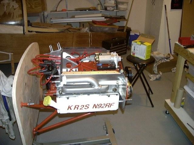
This is what it looks like for now. I need my intake and exhaust before I can do
anymore work on the mock-firewall. Once I have them, I can start finding locations for
the "stuff" that needs to be mounted to the firewall (air-oil seperator, remote oil filter
coils, regulator, gascolator, sensors, etc).
It may be a while before I can work on the motor again, so I'll be going back to working on the airplane now. Until next time...
Back to main pageBack to main Corvair page